4
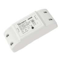
Device Overview
1. Antenna Interface: Connects to
the antenna for wireless
communication.
2. Button:
Single press: Turns the smart
device on or off.
Press and hold for 5 seconds:
Puts the device into pairing mode
(pairing lasts for 10 minutes).
3. LED Screen
Displays power readings. If the
measured power exceeds
10,000W, the screen will show the
value in scientific notation.
Example: "10E3" represents
10kW, and "24E3" represents
24kW.
4. Protective Cover: Shields the
wiring terminals and internal
components.
5. Transformer Interface: Used to
connect the transformer for
power measurement.
6. Power LED Indicator (Red):
On: The device is powered on.
Off: The device is powered off.
7. Wi-Fi LED Indicator (Blue)
Solid: The device is online.
Flashes two short and one
long: The device is in pairing
mode.
Flashes once: The device failed
to connect to the router.
Flashes twice: The device is
connected to the router but
failed to connect to the server.
Flashes three times: The
firmware is updating
8. Mounting Base: Provides
stability when the device is
mounted on the wall or another
surface.
9. Wiring Terminals: The terminals
for wiring connections are visible
once the protective cover is
removed.