5. ELECTRICAL DESCRIPTION
22
LZ T 123 7605 P1C
5. Electrical Description
All electrical connections to the module are protected in compliance with
the standard air (8kV) and contact (4kV) Electrostatic Discharge (ESD)
tests, of EN 61000-4-2.
The module uses the following industry standard connectors:
• High density 15 pin (RS232 serial and extended I/O interface)
• RJ12 6-way (power supply and extended I/O connector)
• RJ9 4-way (handset connector)
• SIM card reader
• FME male coaxial jack (antenna connector)
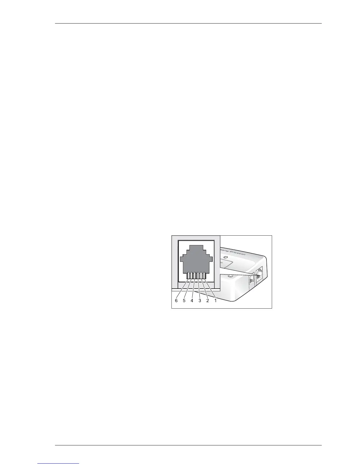
5.1 Power Supply and Extended I/O Connector
An RJ12 6-way connector, as shown and described below, serves as a means
of supplying and controlling d.c. power to the modem. Additionally there
are several extended input/output signals available that can be used to
control or interface external systems and devices.
General signal description:
1 V
IN
2 OUT-2
3 IN-1
4 TO_IN
5 OUT-1
6 GND
 Loading...