(
SECTION 4
ELECTRICAL ADJUSTMENTS
4-1. Basic Adjustments in Replacement of CRT
Perform the following adjustments when replacing the CRT.
[Required Tools and Measuring Instruments]
[Setting of INPUT CONFIGURATION Menu]
1. Signal generator
2. Oscilloscope
Unless specified otherwise, set the INPUT CONFIGURATION
menu of the SETUP menu as follows.
3. Color analyzer (MINOLUTA CA-100)
FORMAT .......................... COMPONENT YUV SMPTE/
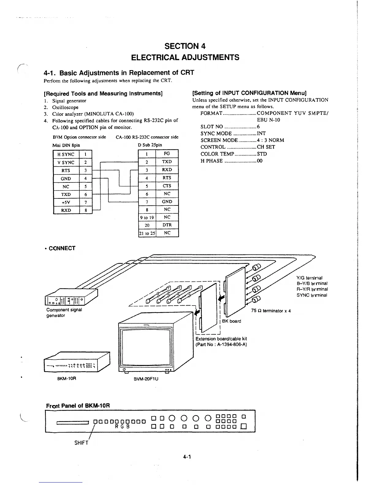
4. Following specified cables for connecting RS-232C pin of
CA-100 and OPTION pin of monitor.
EBU N-10
SLOT NO .........................
6
BVM Option connector side
Mini
DIN Spin
HSYNC
V SYNC
RTS
GND
NC
TXD
+SY
RXD
• CONNECT
Component signal
generator
8KM-10R
1
2
3
4
.,__ .,__
5
6
7
8
.,__
Front Panel of BKM-10R
CA-100 RS-232C connector side
D Sub 25pin
SYNC MODE .................. INT
SCREEN MODE .............
.4 : 3 NORM
CONTROL ....................... CH SET
I
0
1
FG
COLOR TEMP ................. STD
2
TXD
H PHASE ......................... 00
-
3
RXD
4
RTS
5
CTS
6
NC
7
GND
8
NC
9 to 19
NC
20
DTR
21
to 25
NC
-----------,
/#~~
~
L----------, I
------f' I
I I
BVM-20F1U
I I BK board
I I
L ___ _J
Extension board/cable kit
(Part
No: A-1394-806-A)
75
n terminator x 4
0 0 Q Q Q Q ODDO D
000000000 DODO
R GB O O D D O D ODDO 0
SHIFT
4-1
Y/G terminal
B-Y/8
lerrninal
R-Y/R lerminal
SYNC
lerrninal
 Loading...


