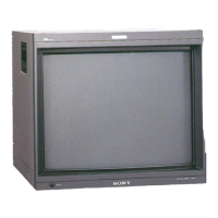
Do you have a question about the Sony BVM-1911 and is the answer not in the manual?
Equipment compliance with FCC Class A limits for digital devices and radio noise.
Critical components identified by shading/mark require specific replacement parts.
Do not use external degausser; use the front panel switch for screen degaussing.
High-performance color video monitors for critical evaluation in broadcasting and production.
Identification and function of front panel buttons, switches, lamps, and selectors.
Identification of rear panel connectors like VIDEO A/B, EXT SYNC, REMOTE, voltage selector, AC IN.
Accessing and identifying controls within the drawer, including warm-up time.
Detailed functions of buttons and selectors on the HY board for configuration and setup.
Details on convergence controls for 4:3 aspect, 16:9 aspect, underscan Y bow, and underscan H amp.
Details on AFC selector, H phase, LIN controls, BLK width/phase, WIDTH, HEIGHT, SIDE PIN, T&B PIN, APERTURE controls.
Identification of switches located on internal circuit boards like BJ and BH boards.
How to access and navigate the initial menu items for monitor settings.
Assigning input signals to front panel selectors using menu operations.
Setting and storing phase, chroma, brightness, and contrast levels in registers via menu.
Storing and selecting white balance settings in registers in combination with picture levels.
Specifying and applying a password to menu options to prevent unauthorized changes.
Configuring remote control functions via STANDARD PARALLEL or CONFIGURE PARALLEL modes.
Specifying operating conditions like installed optional boards, signal levels, and monitor type.
Adjusting convergence for 4:3 scan mode using specified controls for screen portions.
Adjusting convergence for 4:3 underscan mode using specific controls.
Adjusting convergence for 16:9 scan mode, covering center, right, and left portions.
Adjusting white balance at lowlight and highlight using screen switches and controls.
Matching the monitor's black reference with the input signal's black level.
Procedure for removing the top, left, and right covers of the monitor chassis.
Steps for removing the front bezel assembly, including handles and drawer.
Procedure for checking the C board after removing covers.
Steps for removing QA, QB, W, and V boards from the chassis.
Procedure for opening the BK block chassis to access components.
Steps for disconnecting and removing the BK board from the chassis.
Procedure for checking the BK board after removal.
Procedure for checking the DB board after removal.
Procedure for checking the PA board and similar boards like EA and EB.
Procedure for checking the BJ board and similar boards like BA, BC, BG, BH, BI, BT.
Steps for removing the GC board, including PC board retainer and signal block.
Steps for removing the power block assembly.
Procedures for removing the flyback transformer, high voltage block, and anode cap.
Detailed steps for removing and replacing the high voltage cable.
Steps for safely removing the picture tube, including anode cap and neck assembly.
Steps for removing the control panel assembly and related components.
Description of the QA, OB, and BA circuit boards, including input and sync AGC circuits.
Detailed circuit description for the BG board, covering luminance, color gain, G-Y matrix, and NTSC matrix circuits.
Circuit description for the BH board, covering signal switching, contrast, and brightness control circuits.
Circuit description for the BI board, covering AGC pulse insertion, limiter, feedback amplifier, and G2 control circuits.
Description of the BJ board's sync processing and pulse generation circuits.
Circuit description for the BK board, covering drive amplifier, video output amplifier, and buffer circuits.
Description of the beam control circuit on BI and BK boards, including detection and bias control.
Circuit description for the BT board's NTSC comb filter, including dynamic and simple comb filter sections.
Circuit description for the BD board's PAL demodulator, Y trap, and matrix switching circuits.
Circuit description for the BC board's NTSC demodulator, Y trap, and phase compensation circuits.
Circuit description for the EB board's vertical deflection and convergence output circuits.
Circuit description for GA and GB boards, covering AC power supply, degauss, starter, and switching regulator circuits.
Description of convergence circuits on DB, DC boards, and DCT block, including static and dynamic adjustments.
Circuit description for the DA board, covering H delay, AFC, linearity, blanking, and pincushion correction circuits.
Circuit description for the EA board, covering horizontal deflection, centering, and linearity correction circuits.
Circuit description for the PA board's high voltage regulator, including PWM modulator and protection circuits.
Exploded view of the monitor's internal components and their locations.
Diagram showing the location of various circuit boards within the monitor.
A table summarizing board references for circuit descriptions, adjustments, and diagrams.
Diagram showing the location of the sub control panel and its layout.
Procedures for landing adjustment, purity, and DY tilt after picture tube replacement.
Procedures for confirming and adjusting safety-related circuits like the protector and beam current limiter.
Details on adjusting various circuit parameters using front panel and sub control panel settings.
Adjusting the BJ board BRT pulse using an oscilloscope to match a specific waveform.
Adjusting the BJ board sumpling pulse using an oscilloscope to achieve a specific waveform.
Adjusting the level for each channel (BA, BG, BH) using test signals and an oscilloscope.
Adjusting the BA board input circuit frequency response to ensure flatness.
Adjusting the BG board frequency characteristic to match a flat waveform.
Adjusting component input levels for YUV signals on BG board and checking waveform flatness.
Adjusting the BJ board burst gate pulse width to a specific measurement.
Adjusting the BC board band-pass filter (BPF) using sweep signals and an oscilloscope.
Adjusting the BC board phase shift using a color bar signal and an oscilloscope.
Adjusting the BC board's 3.58MHz frequency response (fo) for proper operation.
Adjusting the color difference phase on the BC board using a color bar signal and oscilloscope.
Adjusting the color difference level on the BC board using a color bar signal.
Adjusting the BC board's Y trap to minimize the 3.58MHz subcarrier.
Adjusting the Y-C delay time on the BC board for proper waveform.
Adjusting the BD board's 2T pulse correction for waveform balance.
Adjusting the DA board's V. level to a specific voltage.
Adjusting linearity for 4:3 and 16:9 aspect pictures, including top/bottom pin, side pin, and linearity adjustments.
Adjusting H. center, BLK, and H. phase on the DA board.
Adjusting the H delay position on the DA board for proper pulse width and symmetry.
Signal processing block diagram illustrating the flow of video signals through various boards.
Exploded view and parts list for bezels and covers, including screw types.
Exploded view and parts list for the picture tube assembly, including yoke and magnets.
Exploded view and parts list for the main chassis and its internal boards.
Exploded view and parts list for the signal block, including connectors and boards.
Exploded view and parts list for the drawer assembly, including buttons, switches, and boards.
Exploded view and parts list for the power block assembly, including fuses and switches.
Electrical parts list specifically for the XB and BA boards.
List of diodes used in the circuit.
List of connectors used in the circuit.
List of integrated circuits used in the circuit.
List of coils used in the circuit.
List of transistors used in the circuit.
List of resistors used in the circuit.
List of variable resistors used in the circuit.
List of crystals used in the circuit.


 Loading...