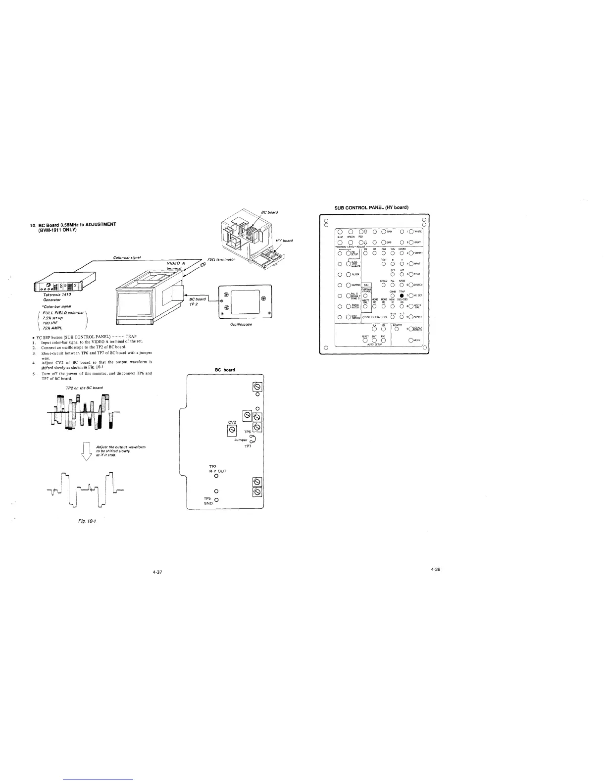
10. BC Board 3.58MHz fo ADJUSTMENT
(BVM-1911 ONLY)
Tektronix 1410
Generator
*Color-bar signal
FULL FIELD color-bar)
7.5% setup
100 IRE
75%AMPL
Co/or-bar signal
• YC SEP button (SUB CONTROL PANEL) ......... TRAP
1. Input color-bar signal to the VIDEO A terminal of the set.
2. Connect an oscilloscope to the TP2 of BC board.
3. Short-circuit between TP6 and TP7 of BC board with a jumper
wire.
4. Adjust CV2 of BC board so that the output waveform is
shifted slowly as shown in Fig. 10-1.
5. Turn off the power of this monitor, and disconnect TP6 and
TP7 of BC board.
TP2 on the BC board
D
Fig. 10-1
Adjust the output waveform
to be shifted slowly
as if it stop.
4-37
BC board
TP2
®D®
®
® @
Oscilloscope
BC board
TP2
R-Y OUT
0
0
TP5 Q
GND
~
0
0
CV2
~~
~
TP6~
Jumper~
TP7
0
0
0
SUB CONTROL PANEL (HY board)
0
0
-----------------~
0 0 Ois O OGArN
0 rOWHITE
BLUE GREEN RED
0 0 OD- o
OBIAS
0
2Q GRAY
RGB
YW
CODED
0 0
0 3OFORMAT
TEST
B
A
0
0
0
0
4o!NPUT
EXT INT
0
0 0
sQsvNc
SECAM PAL
NTSC
0
ASU
0 0
O sOsYSTEM
CHROMA
/PHASE
COMB
TRAP
0
o~~~F
0
COMBS
MEM3
WHITE
0
• 10vc SEP
MEM2 MEMl D65/093
BAL
R3
R2
Rl RO
0
0 CROSS
HATCH 0 0 0 0 0
aQ~irE
16: 9
4; 3
0
OSPUT
CONFIGURATION
0 0
90ASPECT
SCREEN
6
SEL
REMOTE
0
0
oQ~~"¼
RESET
ENT
ESC
0 0 0
OMENU
AUTO SETUP
0
4-38