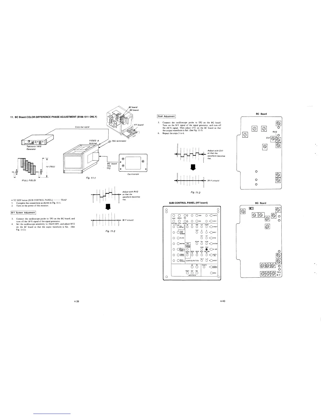
11. BC Board COLOR DIFFERENCE PHASE ADJUSTMENT (BVM-1911 ONLY)
Tektronix 1410
Generator
(FULL FIELD)
T
1 V (75D.)
• YC SEP button (SUB CONTROL PANEL)········· TRAP
1. Complete the connections as shown in Fig. 11-1.
2 Turn on the power of this monitor.
I B-Y System Adjustment I
3. Connect the oscilloscope probe to TP3 on the BG board, and
tum off the (B-Y) signal of the signal generator.
4. Set the oscilloscope sensitivity to 20mV/DIV, and adjust RV2
on the BC board so that the ouput waveform is flat. (See
Fig. 11-2.)
Color-bar signal
Fig. 11-1
1
l
4-39
I I
I I
I I
6l 75n terminator
'-------'-lol·®D®
BG board
TP3 @
TP2 @ @
Oscilloscope
Adjust with R V2
so that the
waveform becomes
flat.
•
I I
I
ir (8-Y circuit)
Fig.
11-2
J Ouad Adjustment I
5.
6.
Connect the oscilloscope probe to TP2 on the BG board.
Turn on the B-Y signal of the signal generator, and tum off
the (R-Y) signal. Then adjust CVl on the BC board so that
the output waveform is flat. (See Fig. 11-3)
Repeat the steps 3 to 6.
0
0
0
•
II I I! 11 11 I
11 I·; 1 · i I
Adjust with CVT
so that the
waveform becomes
flat.
~!Iii • (R-Y circuit)
ii
Fig. 11-3
SUB CONTROL PANEL (HY board)
0
0
0
0
Oil 0
OGAIN
0
tQWHITE
BLUE
GREEN
RED
0 0 OD.
0
Qe1As
0
2Q GRAY
P0S!TI0N -LEVEL-ADJUST
0~
D2 DI RGB
YIN
CODED
0 0 0 0
0 3OFORMAT
TEST
B A
0 5.A.D.
0 0 0
401NPUT
VITC
MARKER
EXT INT
0
0 FILTER
0
0
sQsvNc
SECAM PAL NTSC
0
OMATRIX
ASU
0 0
O sQsvsTEM
.___
CHROMA
/PHASE
COMB TRAP
0
or~~F
0 0
• 1Qvc SEP
COMBS
MEM3 MEM2 MCM I DE5/DB3
WHITE
BAL
R3 R2
RI
RO
0
o~~~~
0 0 0 0
0 aQ~E
-
16: 9 4: 3
0 OfcWlEN
CONFIGURATION
0 0
sQAsPECT
()
SEL
REMOTE
0
0
oQ~cr~
RESET ENT ESC
0 0 0
OMENU
AUTO SETUP
0
4-40
BC Board
[Q] [Q]
CV1~r&
~
0
RV2
0
0
0
~
~
BG Board
~
[QJ[QJ~~~
[Q]