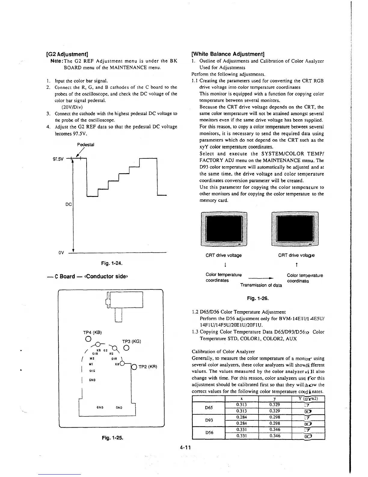
[G2 Adjustment]
Note:The G2 REF Adjustment menu is under the BK
BOARD menu of the MAINTENANCE menu.
I. Input the color bar signal.
2. Connect the R, G, and B cathodes of the C board to the
probes of the oscilloscope, and check the DC voltage of the
color bar signal pedestal.
(20V/Div)
3. Connect the cathode with the highest pedestal DC voltage to
the probe of the oscilloscope.
4. Adjust the G2 REF data so that the pedestal DC voltage
becomes 97 .5V.
Pedestal
/
97.5V --+-----+--,
DC
ov
Fig. 1-24.
- C Board - <Conductor side>
TP4 (KB)
Q ,,.,.0- TP3(KG)
/ KB G2
~
0
Gt8 KG
/ M2
GtR
M1
I GIG
KR
TP2 (KR)
I GNO
GNO GNO
Fig. 1-25.
4-11
[White Balance Adjustment]
1. Outline of Adjustments and Calibration of Color Analyzer
Used for Adjustments
Perform the following adjustments.
1.1 Creating the parameters used for converting the CRT RGB
drive voltage into color temperature coordinates
This monitor is equipped with a function for copying color
temperature between several monitors.
Because the CRT drive voltage depends on the CRT, the
same color temperature will not be attained amongst several
monitors even if the same drive voltage has been supplied.
For this reason, to copy a color temperature between several
monitors, it is necessary to send the required data using
parameters which do not depend on the CRT such as the
xyY color temperature coordinates.
Select and execute the SYSTEM/COLOR TEMP/
FACTORY ADJ menu on the MAINTENANCE menu. The
D93 color temperature will automatically be adjusted and at
the same time, the drive voltage and color temperature
coordinates conversion parameter will be created.
Use this parameter for copying the color temperature to
other monitors and for copying the color temperature to the
memory card.
r:----------·------··--·-··---·-1
l I
:11
~
.::
CRT drive voltage
Color temperature
coordinates
D
CRT drive vollage
l
Color temperature
coordinates
Transmission of data
Fig.1-26.
1.2 D65/D56 Color Temperature Adjustment
Perform the D56 adjustment only for BVM-14El U/14E5U/
14Fl U/14F5U/20E 1U/20FIU.
1.3 Copying Color Temperature Data D65/D93/D56to Color
Temperature STD, COLOR!, COLOR2, AUX
Calibration of Color Analyzer
Generally, to measure the color temperature of a monitor using
several color analyzers, these color analyzers will
sho\lldi fferem
values. The values measured by the color analyzer
¥i JI also
change with time. For this reason, color analyzers
usei ror this
adjustment should be calibrated first so that they will
1hc::>w the
correct values for the following color temperature
cooict-inates.
X
y
y (id/1'112)
D65
0.313 0.329
!.7
0.313
0.329
100
D93
0.284 0.298
!.7
0.284 0.298
100
D56
0.331
0.346
!.7
0.331
0.346
100
 Loading...


