© 2004 Sony Corporation Printed in Korea
3-263-410-21 (1)
Cautions
•This unit is designed for negative ground 12 V
DC operation only.
•Do not get the leads under a screw, or caught
in moving parts (e.g. seat railing).
•Before making connections, turn the car
ignition off to avoid short circuits.
•Connect the yellow and red power input leads
only after all other leads have been connected.
•Run all ground leads to a common ground
point.
•Be sure to insulate any loose unconnected
leads with electrical tape for safety.
•The use of optical instruments with this
product will increase eye hazard.
Notes on the power supply lead (yellow)
•When connecting this unit in combination with
other stereo components, the connected car
circuit’s rating must be higher than the sum of
each component’s fuse.
•When no car circuits are rated high enough,
connect the unit directly to the battery.
Parts Iist (1)
•The numbers in the list are keyed to those in
the instructions.
•The bracket 1 and the protection collar 3 are
attached to the unit before shipping. Before
mounting the unit, use the release keys 5 to
remove the bracket 1 and the protection collar
3 from the unit. For details, see “Removing
the protection collar and the bracket (4)” on
the reverse side of the sheet.
•Keep the release keys 5 for future use as
they are also necessary if you remove the
unit from your car.
Caution
Handle the bracket 1 carefully to avoid injuring
your fingers.
Note
Before installing, make sure that t he cat ches on
both sides of the bracket 1 are bent inw ards 2 mm
(
3
/32 in). If the catches are straight or bent out w ards,
the unit w ill not be inst alled securely and may spring
out.
Installat ion/Connections
Instalación/Conexiones
FM/AM
Compact Disc
Player
Connection example (2)
Notes (2-A)
• Be sure t o connect t he ground lead bef ore
connecting the amplif ier.
• If you connect an opt ional pow er amplif ier and do
not use the built-in amplif ier, t he beep sound w ill
be deactivated.
Tip (2-B-
)
For connecting two or more CD/MD changers, the
source selector XA-C30 (optional) is necessary.
Connection diagram (3)
1 To a metal surface of the car
First connect the black ground lead, then
connect the yellow and red pow er input leads.
2 To the power antenna control lead or power
supply lead of antenna booster amplifier
Notes
• It is not necessary to connect t his lead if t here
is no power antenna or antenna booster, or
with a manually-operat ed t elescopic ant enna.
• When your car has a built -in FM /AM ant enna in
the rear/side glass, see “ Not es on t he cont rol
and power supply leads.”
3 To AMP REMOTE IN of an optional power
amplifier
This connection is only for amplifiers. Connecting
any other system may damage the unit.
4 To the interface cable of a car telephone
5 To a car’s illumination signal
Be sure to connect the black ground lead t o a
metal surface of the car f irst .
6 To the +12 V power terminal which is energized
in the accessory position of the ignition key
switch
Notes
• If t here is no accessory position, connect t o t he
+12 V pow er (bat t ery) t erminal w hich is
energized at all times.
Be sure to connect the black ground lead t o a
metal surface of the car f irst .
• When your car has a built -in FM /AM ant enna in
the rear/side glass, see “ Not es on t he cont rol
and power supply leads.”
7 To the +12 V power terminal which is energized
at all times
Be sure to connect the black ground lead t o a
metal surface of the car f irst .
1 32
Equipment used in illustrations (not supplied)
Equipo utilizado en las ilust raciones (no suministrado)
Rear speaker
Altavoz posterior
Front speaker
Altavoz frontal
1
Power amplifier
Amplificador de potencia
5
× 2
4
Active subwoofer
Altavoz potenciador de
graves activo
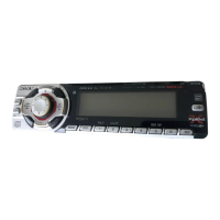
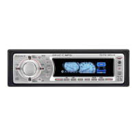
CDX-FW700
Catch
1
× 4
AUDIO OUT
FRONT
AUDIO OUT
REAR
SUB OUT (M ONO)
BUS AUDIO IN
BUS CONTROL IN
BUS AUDIO IN
BUS CONTROL IN
Source selector*
Selector de fuente*
XA-C30
* not supplied
no suministrado
2
A
B
CD/MD changer
Cambiador de CD/MD
Rotary commander RM-X4S
Mando rotatorio RM-X4S
Downloaded from: https://www.usersmanualguide.com/