EasyManua.ls Logo

Sony CDX-GT110 User Manual

Sony CDX-GT110
44 pages
To Next Page IconTo Next Page
Page #1 background imageLoading...
Page #1 background image
SERVICE MANUAL
Sony Corporation
eVehicle Division
Published by Sony Techno Create Corporation
US Model
CDX-GT11W/GT110
Canadian Model
CDX-GT110
E Model
CDX-GT160/GT160S
Chinese Model
CDX-GT160
9-887-374-03
2007B04-1
© 2007.02
Ver. 1.2 2007.02
SPECIFICATIONS
CD player section
Signal-to-noise ratio 95 dB
Frequency response 10 – 20,000 Hz
Wow and flutter Below measurable limit
Tuner section
FM
Tuning range 87.5 – 107.9 MHz (CDX-GT11W/GT110)
87.5 – 108 MHz (at 50 kHz step)
(CDX-GT160/GT160S)
87.5 – 107.9 MHz (at 200 kHz step)
(CDX-GT160/GT160S)
FM tuning interval 50 kHz/200 kHz switchable
(CDX-GT160/GT160S)
Antenna terminal External antenna connector
Intermediate frequency 10.7 MHz/450 kHz
Usable sensitivity 9 dBf
Selectivity 75 dB at 400 kHz
Signal-to-noise ratio 67 dB (stereo), 69 dB (mono)
Harmonic distortion at 1 kHz
0.5% (stereo), 0.3% (mono)
Separation 35 dB at 1 kHz
Frequency response 30 – 15,000 Hz
AM/MW
Tuning range 530 – 1,710 kHz (CDX-GT11W/GT110)
531 – 1,602 kHz (at 9 kHz step)
(CDX-GT160/GT160S)
530 – 1,710 kHz (at 10 kHz step)
(CDX-GT160/GT160S)
AM tuning interval 9 kHz/10 kHz switchable
(CDX-GT160/GT160S)
Antenna terminal External antenna connector
Intermediate frequency 10.7 MHz/450 kHz
Sensitivity 30 µV
SW (CDX-GT160/GT160S)
Tuning range SW1: 2,940 – 7,735 kHz
SW2: 9,500 – 18,135 kHz
(expect for 10,140 – 11,575 kHz)
Antenna (aerial) terminal
External antenna (aerial) connector
Intermediate frequency 10.7 MHz/450 kHz
Sensitivity 30 µV
The tuner and CD sections have no adjustments.
Model Name Using Similar Mechanism NEW
CD Drive Mechanism Type MG-101TA-188//Q
Optical Pick-up Name DAX-25A
– Continued on next page –
CDX-GT11W/GT110/
GT160/GT160S
AUDIO POWER SPECIFICATIONS (US MODEL)
POWER OUTPUT AND TOTAL HARMONIC DISTORTION
22 (23)* watts per channel minimum continuous average power into
4 ohms, 4 channels driven from 20 Hz to 20 kHz with no more
than 5% total harmonic distortion.
* CDX-GT11W
FM/AM COMPACT DISC PLAYER
CDX-GT11W/GT110
FM/MW/SW COMPACT DISC PLAYER
CDX-GT160/GT160S

Other manuals for Sony CDX-GT110

Question and Answer IconNeed help?

Do you have a question about the Sony CDX-GT110 and is the answer not in the manual?

Sony CDX-GT110 Specifications

General IconGeneral
Preset Stations30
CD PlaybackYes
MP3 PlaybackYes
WMA PlaybackYes
USB PortNo
Display TypeLCD
EqualizerYes
AUX InputYes
Removable Front PanelYes
Detachable FaceplateYes
Product ColorBlack
BluetoothNo
Channels4
RMS Power Output17 Watts x 4
TunerAM/FM

Summary

Product Identification and System Specifications

Supported Model Variants

Identifies different regional models of the car audio unit.

Audio Power Output and Distortion

Details the output power and total harmonic distortion for US models.

CD Player Performance Metrics

Lists performance metrics for the CD player section.

Tuner Sensitivity and Frequency Ranges

Outlines FM, AM/MW, and SW tuning capabilities and sensitivity.

Technical Specifications and Service Notes

Power Amplifier and General Unit Specifications

Details power output, inputs, tone controls, and general unit properties.

Recommended Test Discs for CD Section

Lists recommended test discs for CD section checks.

Optical Pick-Up and Laser Diode Handling Precautions

Provides critical notes on handling the optical pick-up and laser diode.

Critical Safety Component Identification

Highlights critical components for safe operation and replacement.

Key Features and Service Precautions

CD Playback Format Support

Describes the types of CDs playable and CD TEXT information.

Unleaded Solder Characteristics and Handling

Details characteristics and precautions for using unleaded solder.

Service Extension Cable Connection

Explains how to connect extension cables for servicing the unit.

Key Replacement Procedures and Notes

Servo Board Replacement Procedure

Instructions for replacing the complete servo board.

AUX Jack Replacement and Alignment Steps

Steps for replacing the AUX jack, including alignment.

CDX-GT11W: Control Layout and Connections

CDX-GT11W Front Panel Control Functions

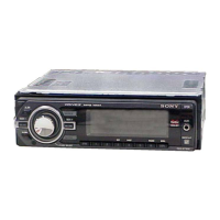
Details the location and function of each button and control on the CDX-GT11W.

CDX-GT11W Wiring Connection Diagram

Illustrates the wiring connections for the CDX-GT11W.

Vehicle Wiring and Connection Guide

General Vehicle Wiring Diagram

Illustrates the primary wiring connections for power and antenna.

Power, Control, and Antenna Lead Notes

Provides important notes on power supply, antenna control, and memory circuits.

Speaker Connection Best Practices

Offers specific instructions and warnings for connecting speakers.

CDX-GT110: Control Layout and Connections

CDX-GT110 Front Panel Control Functions

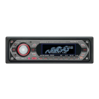
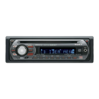
Details the location and function of each button and control on the CDX-GT110.

CDX-GT110 Wiring Connection Diagram

Illustrates the wiring connections for the CDX-GT110.

Vehicle Wiring: Multi-language Instructions

French Wiring Diagram and Notes

Diagrama de conexión principal con notas en francés.

French Notes on Power, Control, and Antenna Leads

Notas sobre alimentación, control de antena y memoria en francés.

French Speaker Connection Guidelines

Instrucciones de conexión de altavoces en francés.

CDX-GT160/GT160S: Control Layout and Connections

CDX-GT160/GT160S Front Panel Controls

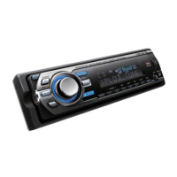
Details the location and function of each button and control on the CDX-GT160/GT160S.

CDX-GT160/GT160S Wiring Diagram

Illustrates the wiring connections for the CDX-GT160/GT160S.

Vehicle Wiring: Chinese Instructions

Chinese Wiring Diagram and Notes

汽车音频连接图及注意事项 (中文)。

Chinese Notes on Power, Control, and Antenna Leads

电源、控制导线及扬声器连接注意事项 (中文)。

Chinese Speaker Connection Guidelines

扬声器连接指南和注意事项 (中文)。

Unit Disassembly Procedure Overview

Disassembly Flowchart and Sequence

Provides a flowchart for disassembling the unit in a specific order.

Disassembly: Panel and CD Mechanism Removal

Sub Panel (LCD) Assembly Removal Steps

Details the steps to remove the sub panel (LCD) assembly.

CD Mechanism Block Removal Procedure

Explains how to remove the CD mechanism block.

Disassembly: Main and Servo Board Removal

Main Board Removal Steps

Provides instructions for removing the main board.

Servo Board Removal Steps

Details the steps to remove the servo board.

Disassembly: Chassis and Roller Arm Assembly

Chassis (T) Sub Assembly Removal Steps

Details the steps to remove the chassis (T) sub assembly.

Roller Arm Assembly Removal Steps

Explains how to remove the roller arm assembly.

Disassembly: Chassis (OP) Assembly Removal

Chassis (OP) Assembly Removal Steps

Details the steps to remove the chassis (OP) assembly.

Unit Diagnosis Functionality

Entering and Exiting Diagnosis Mode

Instructions for entering, exiting, and navigating the diagnosis display modes.

Diagnosis Mode Information Displayed

Describes the information shown in reset count, watchdog timer, and connected units modes.

Diagnostic Error and Status Modes

Viewing CD Error Codes and Types

Details how to view CD error descriptions and disc types.

Checking Offset and Failure Error History

Explains how to check offset/failure error histories.

System Block Diagrams: Main Section

Main Section Functional Block Diagram

Illustrates the main functional blocks and signal flow of the unit.

System Block Diagrams: Display Section

Display Section Functional Block Diagram

Shows the block diagram for the display control and key matrix.

Schematic and Waveform Measurement Notes

Provides important notes regarding schematic symbols and waveform measurements.

Printed Wiring Board Layouts: Main Section

Main Section PWB Component Placement Diagram

Diagram showing component placement on the main section printed wiring board.

Schematic Diagrams: Main Section (1 of 3)

Main Section Schematic - Volume and Audio Buffer

Detailed schematic for the main section, covering volume control and audio buffer.

Schematic Diagrams: Main Section (2 of 3)

Main Section Schematic - Power Amplifier and Regulator

Detailed schematic for the main section, covering power amplifier and voltage regulator.

Schematic Diagrams: Main Section (3 of 3)

Main Section Schematic - Chip Detect and Diagnostics

Detailed schematic for the main section, covering chip detect and diagnostic circuits.

Printed Wiring Board Layouts: Key Section

Key Section PWB Component Placement Diagram

Diagram showing component placement on the key section printed wiring board.

Schematic Diagrams: Key Section

Key Section Schematic - Buttons and Display

Detailed schematic for the key section, including button and display controls.

Integrated Circuit Block Diagrams

IC401 BD3444FS-E2 Internal Structure

Illustrates the internal functions and signal paths of the IC401 audio processor.

Integrated Circuit Block Diagrams: Power Amplifier

IC750 TDA8588BJ/TDA8589BJ Internal Structure

Shows the internal architecture of the IC750 power amplifier IC.

Integrated Circuit Pin Descriptions: System Control

IC501 System Control IC Pinout

Details the function of each pin for the IC501 system control IC.

Integrated Circuit Pin Descriptions: System Control (Cont.)

IC501 System Control IC Pinout (Continued)

Details the remaining pin functions for the IC501 system control IC.

Exploded View Diagrams: Main Section

Main Section Parts Breakdown Diagram

Diagram showing parts breakdown of the main section with part numbers.

Exploded View Diagrams: Front Panel

Front Panel Parts Breakdown Diagram

Diagram showing parts breakdown of the front panel assembly.

Exploded View Diagrams: CD Mechanism

CD Mechanism Parts Breakdown Diagram

Diagram showing parts breakdown of the CD mechanism.

Electrical Parts List: Key Section Components

Key Board Electrical Component Details

Lists electrical components (LEDs, switches, ICs) for the key board.

Electrical Parts List: Resistors, Switches, and Transistors

Resistor, Transistor, and Switch Component Details

Lists resistors, transistors, and switches used in the unit.

Electrical Parts List: Main Board Components (Capacitors & Diodes)

Main Board Capacitors and Diodes List

Lists capacitors and diodes used on the main board.

Electrical Parts List: Servo Board Components (Fuses, ICs, etc.)

Servo Board Fuses, ICs, and Resistors List

Lists fuses, transistors, ICs, and resistors for the servo board.

Electrical Parts List: Main Board Resistors (Continued)

Main Board Resistor Component Details

Lists various resistors used on the main board.

Included Accessories and Installation Parts

Unit Accessories and User Manuals

Lists the included manuals and accessories provided with the unit.

Installation Kit and Connection Hardware

Lists parts required for installation and connecting the unit.

Service Supplement: Optical Pick-Up Removal

Chucking Arm Sub Assembly Disassembly

Details the steps for removing the chucking arm sub assembly.

Service Supplement: Sled Motor Assembly

Sled Motor Assembly Disassembly and Reassembly

Provides instructions for removing and reassembling the sled motor assembly.

Service Supplement: Optical Pick-Up Components

Optical Pick-Up Section Disassembly

Details the steps for removing the optical pick-up section.

Optical Pick-Up Assembly and Slide Notes

Provides assembly notes for the optical pick-up and lead screw.

Related product manuals