EasyManua.ls Logo

Sony CDX-GT500 Service Manual

Sony CDX-GT500
59 pages
To Next Page IconTo Next Page
Page #1 background imageLoading...
Page #1 background image
Great user manuals database on UserManuals.info
1
Ver. 1.0 2005. 12
Model Name Using Similar Mechanism CDX-A250/A250EE
CD Drive Mechanism Type MG-611WA-186//Q
Optical Pick-up Name KSS1000E
SERVICE MANUAL
US Model
CDX-GT50W/GT500
Canadian Model
AEP Model
UK Model
CDX-GT500
E Model
CDX-GT550
East European Model
CDX-GT500EE
Chinese Model
CDX-GT550
CDX-GT50W/GT500/
GT500EE/GT550
SPECIFICATIONS
• The tuner and CD sections have no adjustments.
Sony Corporation
eVehicle Division
Published by Sony Engineering Corporation
9-887-003-01
2005L04-1
© 2005. 12
FM/MW/LW COMPACT DISC PLAYER
CDX-GT500: AEP, UK MODEL
FM/AM COMPACT DISC PLAYER
CDX-GT50W/GT500: US, Canadian MODEL/GT500EE/GT550
AUDIO POWER SPECIFICATIONS (US Model)
POWER OUTPUT AND TOTAL HARMONIC DISTORTION
23.2 watts per channel minimum continuous average power into
4 ohms, 4 channels driven from 20 Hz to 20 kHz with no more
than 5% total harmonic distortion.
CD player section
Signal-to-noise ratio: 120 dB
Frequency response: 10 – 20,000 Hz
Wow and flutter: Below measurable limit
Tuner section
FM
Tuning range: CDX-GT50W/GT500: US Canadian model
87.5 – 107.9 MHz
CDX-GT500: AEP, UK model
87.5 – 108.0 MHz
CDX-GT500EE:
FM1/FM2: 87.5 – 108.0 MHz (at 50 kHz step)
FM3: 65 – 74 MHz (at 30 kHz step)
CDX-GT550:
87.5 – 108.0 MHz (at 50 kHz step)
87.5 – 107.9 MHz (at 200 kHz step)
FM tuning interval (CDX-GT550 only):
50 kHz/200 kHz switchable
Antenna terminal: External antenna connector
Intermediate frequency: 10.7 MHz/450 kHz
Usable sensitivity: 9 dBf
Selectivity: 75 dB at 400 kHz
Signal-to-noise ratio: 67 dB (stereo), 69 dB (mono)
Harmonic distortion at 1 kHz:
0.5 % (stereo), 0.3 % (mono)
Separation: 35 dB at 1 kHz
Frequency response: 30 – 15,000 Hz
AM (CDX-GT50W/GT500: US, Canadian model/GT500EE/GT550)
Tuning range: CDX-GT50W/GT500: US, Canadian model:
530 – 1,710 kHz
CDX-GT500EE:
531 – 1,602 kHz
CDX-GT550:
531 – 1,602 kHz (at 9 kHz step)
530 – 1,710 kHz (at 10 kHz step)
AM tuning interval (CDX-GT550 only):
9 kHz/10 kHz switchable
Antenna terminal: External antenna connector
Intermediate frequency: 10.7 MHz/450 kHz
Sensitivity: 30 µV
MW/LW (CDX-GT500: AEP, UK model)
Tuning range: MW: 531 – 1,602 kHz
LW: 153 – 279 kHz
Aerial terminal: External aerial connector
Intermediate frequency: 10.7 MHz/450 kHz
Sensitivity: MW: 30 µV, LW: 40 µV
– Continued on next page –
Photo: CDX-GT500

Other manuals for Sony CDX-GT500

Question and Answer IconNeed help?

Do you have a question about the Sony CDX-GT500 and is the answer not in the manual?

Sony CDX-GT500 Specifications

General IconGeneral
MP3 playbackYes
Frequency range10 - 20000 Hz
Equalizer bands quantity3
Signal-to-Noise Ratio (SNR)120 dB
Tuner typeSSIR-EXA
Preset stations quantity30
Illumination colorBlue
Weight and Dimensions IconWeight and Dimensions
Dimensions (WxDxH)178 x 181 x 50 mm

Summary

Specifications

CD Player Performance

Details on CD player performance metrics like SNR and frequency response.

Tuner Performance (FM)

FM tuning range, sensitivity, selectivity, and frequency response details.

Tuner Performance (AM/MW/LW)

AM, MW, and LW tuning ranges, sensitivity, and selectivity details.

Power Amplifier Section

General Power Specifications

Details on power output, impedance, and general unit parameters.

Service Notes

Handling and Replacement Guidance

Precautions for optical pick-up, laser diodes, chip components, and test discs.

CD Playback Capabilities

Service Position and Extension Cable

Unleaded Solder Information

General Information

Controls and Basic Operations

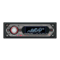
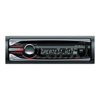
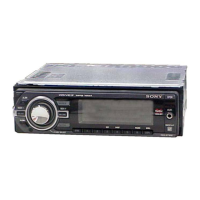
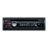
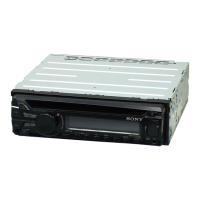
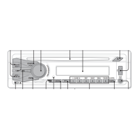
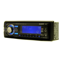
Details the location and function of unit controls and remote commander.

Connections

Wiring Diagram

Illustrates how to connect the unit to various car systems and accessories.

Power and Control Leads

Notes on connecting power, antenna control, and illumination leads.

Speaker Connection Notes

Important considerations for connecting speakers to the unit.

Disassembly Procedures

Panel and CD Mechanism Disassembly

Steps for disassembling the front panel and CD mechanism block.

Board and Chassis Disassembly

Procedures for removing the main board and chassis components.

Mechanism Component Disassembly

Details for disassembling roller arms, motors, and optical pick-ups.

Servo Board Disassembly

Instructions for disassembling the servo board.

Diagrams

Block Diagrams

Functional block diagrams for CD, Main, and Display sections.

Circuit Boards Location

Visual guide showing the placement of all circuit boards within the unit.

Printed Wiring Boards

CD Mechanism Section Boards

Printed wiring board layouts for the CD mechanism section, including servo and sensor boards.

Sub Section Boards

Printed wiring board layouts for the sub section, detailing component placement.

Key Section Boards

Printed wiring board layouts for the key section, including component locations.

Schematic Diagrams

CD Mechanism Section

Schematic diagrams for the CD mechanism section (Parts 1/2 and 2/2).

Main Section

Schematic diagrams for the main unit section (Parts 1/2, 2/3, and 3/3).

Sub Section

Schematic diagram detailing the connections and components of the sub section.

Key Section

Schematic diagram illustrating the circuitry of the key section.

IC Block Diagrams

Servo Board ICs

Block diagrams for ICs on the servo board, detailing their functional blocks.

Main Board ICs

Block diagrams for ICs on the main board, illustrating internal structures.

IC Pin Descriptions

IC3 Servo Board Pinout

Detailed pin description for IC3 (MB90486BPFV-G-177E1) on the servo board.

IC711 Main Board Pinout

Detailed pin description for IC711 (MB90487APF-G-162E1) on the main board.

Exploded Views

Main Section Assembly

Exploded view and parts list for the main section of the unit.

Front Panel Assembly

Exploded view and parts list for the front panel assembly.

CD Mechanism Assemblies

Exploded views and parts lists for various sections of the CD mechanism.

Electrical Parts List

Key Board Components

List of components for the key board, including capacitors, LEDs, ICs, and connectors.

Resistors, Switches, and Vibrators

List of resistors, switches, vibrators, and tuner unit components.

Capacitors

Detailed list of capacitors with part numbers, values, and voltage ratings.

Diodes, Transistors, and ICs

List of diodes, transistors, ICs, jacks, and coils with their respective part numbers.

Resistors, Switches, and Miscellaneous Components

List of resistors, switches, transformer, thermistor, tuner unit, and vibrator components.

Servo and Sub Board Components

List of components for the servo and sub boards, including resistors and switches.

Accessories and Installation Parts

Remote Commander and Manuals

List of accessories including remote commander and user manuals.

Installation Hardware

List of parts for installation and connections, such as frames, screws, and cords.

Revision History

Document Revision Log

Records of revisions made to the service manual, including version and date.

Related product manuals