Do you have a question about the Sony CDX-GT564UI and is the answer not in the manual?
Notes on handling the optical pick-up block to prevent damage and ensure proper operation.
Safety precautions and procedures for checking laser diode emission to avoid eye damage.
Information on the characteristics and usage of unleaded solder.
Procedure for setting and confirming the destination code after replacing the system controller.
Instructions for connecting the extension cable and positioning for service.
Notes on replacing USB/AUX connectors and guidance for servo/switch boards.
Information on test discs and precautions for handling the 20-pin connector.
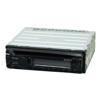
General cautions, connection examples, and diagrams for unit installation.
Adjusting mounting angle and procedures for detaching/attaching the front panel.
Procedures for installing the unit in dashboards and specific notes for Japanese cars.
Diagrams and warnings for connecting the power supply, including car-specific variations.
Flowchart outlining the sequence for disassembling the unit.
Procedures for removing the unit's cover and sub panel block.
Procedure for removing the CD mechanism deck (MG-101CA-188).
Procedures for removing main board, servo board, chassis, and roller arm.
Procedures for removing the sled motor, optical pick-up section, and component.
Block diagrams for audio input, output, panel, and power supply circuits.
Component layout for the main board (part 1 of 2).
Component layout for the main board (part 2 of 2).
Component layout for the main board (Saudi Arabia models) - part 1.
Component layout for the main board (Saudi Arabia models) - part 2.
Schematic diagram of the main board circuits (part 1 of 4).
Schematic diagram of the main board circuits (part 2 of 4).
Schematic diagram of the main board circuits (part 3 of 4).
Schematic diagram of the main board circuits (part 4 of 4).
Component layout for the key board.
Schematic diagram of the key board circuits.
Internal block diagrams for key integrated circuits.
Detailed descriptions of pin functions for main ICs.
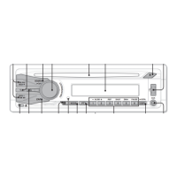
Exploded view of the main section of the unit, showing part locations.
Exploded view of the front panel assembly and its components.
Exploded view of the CD mechanism section (MG-101CA-188).
List of electrical parts for the key board, connectors, capacitors, diodes, and ferrite beads.
List of ICs, LEDs, switches, transistors, resistors, vibrators, boards, and accessories.
Record of revisions made to the service manual.
| AUX in | Yes |
|---|---|
| Bluetooth | No |
| File type | MP3/WMA/AAC |
| FM band range | 87.5 - 107.9 MHz |
| Supported radio bands | FM, LW, MW |
| Output power | 52 W |
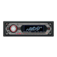
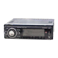
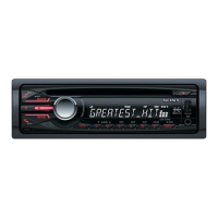
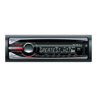
| Product color | Black |
| Audio output channels | 4.0 channels |
| Display type | LCD |