SERVICE MANUAL
Sony Corporation
Published by Sony Techno Create Corporation
Tuner section
(US and Canadian models)
(AEP and UK models)
(US and Canadian models only)
(US and Canadian models only)
FM
Tuning range: 87.5 – 107.9 MHz
Antenna (aerial) terminal:
External antenna (aerial) connector
Intermediate frequency: 25 kHz
Usable sensitivity: 8 dBf
Selectivity: 75 dB at 400 kHz
Signal-to-noise ratio: 80 dB (stereo)
Separation: 50 dB at 1 kHz
Frequency response: 20 – 15,000 Hz
AM
Tuning range: 530 – 1,710 kHz
Antenna (aerial) terminal:
External antenna (aerial) connector
Intermediate frequency:
9,115 kHz or 9,125 kHz/5 kHz
Sensitivity: 26 μV
CD Player section
Signal-to-noise ratio: 120 dB
Frequency response: 10 – 20,000 Hz
Wow and utter: Below measurable limit
USB Player section
Interface: USB (Full-speed)
Maximum current: 1 A
Power amplier section
Output: Speaker outputs
Speaker impedance: 4 – 8 ohms
Maximum power output: 52 W × 4 (at 4 ohms)
General
Outputs:
Audio outputs terminal (rear/sub switchable)
Power antenna (aerial)/Power amplier control
terminal (REM OUT)
Inputs:
Remote controller input terminal
Antenna (aerial) input terminal
AUX input jack (stereo mini jack)
USB
port
Power requirements: 12 V DC car battery
(negative ground (earth))
Dimensions: Approx. 178 × 50 × 177 mm
(7
1
/8 × 2 × 7 in) (w/h/d)
Mounting dimensions: Approx. 182 × 53 × 160 mm
(7
1
/4 × 2
1
/8 × 6
5
/16 in) (w/h/d)
Mass: Approx. 1.2 kg (2 lb 11 oz)
Supplied accessories:
Remote commander: RM-X211
(CDX-52UM/GT470UM: US, Canadian/
GT472UE/GT520U/GT525U only)
Parts for installation and connections (1 set)
Design and specications are subject to change
without notice.
FOR UNITED STATES CUSTOMERS. NOT
APPLICABLE IN CANADA, INCLUDING
IN THE PROVINCE OF QUEBEC.
POUR LES CONSOMMATEURS AUX
ÉTATS-UNIS. NON APPLICABLE AU
CANADA, Y COMPRIS LA PROVINCE DE
QUÉBEC.
CEA2006 Standard
Power Output: 17 Watts RMS 4 at
4 Ohms < 1% THD+N
SN Ratio: 80 dBA
(reference: 1 Watt into 4 Ohms)
AUDIO POWER SPECIFICATIONS
Tuner section
FM
Tuning range: 87.5 – 108.0 MHz
Antenna (aerial) terminal:
External antenna (aerial) connector
Intermediate frequency: 25 kHz
Usable sensitivity: 8 dBf
Selectivity: 75 dB at 400 kHz
Signal-to-noise ratio: 80 dB (stereo)
Separation: 50 dB at 1 kHz
Frequency response: 20 – 15,000 Hz
MW/LW
Tuning range:
MW: 531 – 1,602 kHz
LW: 153 – 279 kHz
Antenna (aerial) terminal:
External antenna (aerial) connector
Intermediate frequency:
9,124.5 kHz or 9,115.5 kHz/4.5 kHz
Sensiti
vity: MW: 26 μV, LW: 45 μV
(Russian model)
Tuner section
FM
Tuning range:
FM1/FM2: 87.5 – 108.0 MHz (at 50 kHz step)
FM3: 65 – 74 MHz (at 30 kHz step)
Tuning range: 87.5 – 108.0 MHz
CDX-GT472UE/CDX-GT470UE
CDX-GT470UM
Antenna (aerial) terminal:
External antenna (aerial) connector
Intermediate frequency: 25 kHz
Usable sensitivity: 8 dBf
Selectivity: 75 dB at 400 kHz
Signal-to-noise ratio: 80 dB (stereo)
Separation: 50 dB at 1 kHz
Frequency response: 20 – 15,000 Hz
MW/LW
Tuning range:
MW: 531 – 1,602 kHz
LW: 153 – 279 kHz
Antenna (aerial) terminal:
External antenna (aerial) connector
Intermed
iate frequency:
9,124.5 kHz or 9,115.5 kHz/4.5 kHz
Sensitivity: MW: 26 μV, LW: 45 μV
Tuner section
(E, Mexican, Argentina, Korean
and Indian models)
FM
Tuning range:
For non-Argentine models:
87.5 – 108.0 MHz (at 50 kHz step)
87.5 – 108.0 MHz (at 100 kHz step)
87.5 – 107.9 MHz (at 200 kHz step)
For Argentine models:
87.5 – 107.9 MHz
FM tuning step (for non-Argentine models):
50 kHz/100 kHz/200 kHz switchable
Antenna (aerial) terminal:
External antenna (aerial) connector
Intermediate frequency: 25 kHz
Usable sensitivity: 8 dBf
Selectivity: 75 dB at 400 kHz
Signal
-to-noise ratio: 80 dB (stereo)
Separation: 50 dB at 1 kHz
Frequency response: 20 – 15,000 Hz
AM
Tuning range:
For non-Argentine models:
531 – 1,602 kHz (at 9 kHz step)
530 – 1,710 kHz (at 10 kHz step)
For Argentine models:
530 – 1,710 kHz
AM tuning step (for non-Argentine models):
9 kHz/10 kHz switchable
Antenna (aerial) terminal:
External antenna (aerial) connector
Intermediate frequency:
For non-Argentine models:
9,124.5 kHz or 9,115.5 kHz/4.5 kHz
(at 9 kHz step)
9,115 kHz or 9,125 kHz/5 kHz
(at 10 kHz step)
For Argent
ine models:
9,115 kHz or 9,125 kHz/5 kHz
Sensitivity: 26 μV
Tuner section
(Saudi Arabia model)
FM
Tuning range:
87.5 – 108.0 MHz
Antenna (aerial) terminal:
External antenna (aerial) connector
Intermediate frequency: 25 kHz
Usable sensitivity: 8 dBf
Selectivity: 75 dB at 400 kHz
Signal-to-noise ratio: 80 dB (stereo)
Separation: 50 dB at 1 kHz
Frequency response: 20 – 15,000 Hz
MW
Tuning range:
531 – 1,602 kHz
Antenna (aerial) terminal:
External antenna (aerial) connector
Intermediate frequency:
9,124
.5 kHz or 9,115.5 kHz/4.5 kHz
Sensitivity: 26 μV
SW
Tuning range:
SW1: 2,940 – 7,735 kHz
SW2: 9,500 – 18,135 kHz
(except for 10,140 – 11,575 kHz)
Antenna (aerial) terminal:
External antenna (aerial) connector
Intermediate frequency:
9,124.5 kHz or 9,115.5 kHz/4.5 kHz
Sensitivity: 26 μV
CDX-GT52UM/GT470UE/GT470UM/GT472UE/
GT472UM/GT474UM/GT520U/GT525U
SPECIFICATIONS
9-893-531-01
2012G33-1
©
2012.07
US Model
Canadian Model
CDX-GT470UM
AEP Model
UK Model
CDX-GT470UM/GT472UM/GT474UM
E Model
CDX-GT520U
Russian Model
CDX-GT470UE/GT470UM/GT472UE
Indian Model
CDX-GT52UM/GT525U
Ver. 1.0 2012.07
Model Name Using Similar Mechanism CDX-GT40U/GT44U/GT45U
Mechanism Type MG-101CA-188
Optical Pick-up Name DAX-25A
• The tuner and CD sections have no adjustments.
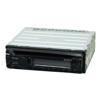
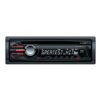
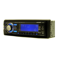
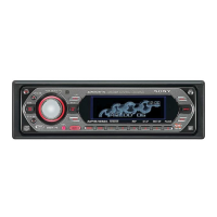
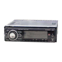
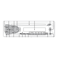
Photo: CDX-GT470UM
US, Canadian, E, Mexican, Argentina, Korean and Indian models
FM/AM COMPACT DISC PLAYER
AEP, Russian and UK models
FM/MW/LW COMPACT DISC PLAYER
Saudi Arabia model
FM/MW/SW COMPACT DISC PLAYER