SERVICE MANUAL
Sony Corporation
Published by Sony Techno Create Corporation
CDX-GT61UMS/GT560UE/GT560UI/GT560US/
GT564UI/GT610UG/GT610US/GT616UG
SPECIFICATIONS
9-893-265-01
2011H33-1
©
2011.08
AEP Model
UK Model
CDX-GT560UI/GT564UI
E Model
CDX-GT610UG/GT610US
Russian Model
CDX-GT560UE/GT560UI/GT560US
Mexican Model
Argentina Model
CDX-GT610UG
Indian Model
CDX-GT61UMS/GT616UG
Ver. 1.0 2011.08
Model Name Using Similar Mechanism
CDX-GT45U/GT660UE/
GT660UV/GT710UV/GT717UV
Mechanism Type MG-101CA-188
Optical Pick-up Name DAX-25A
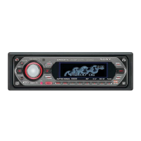
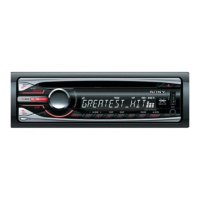
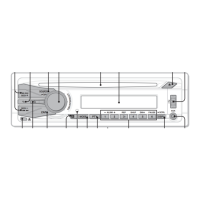
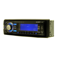
Photo: CDX-GT610UG
• The tuner and CD sections have no adjustments.
Tuner section
(CDX-GT560UE/GT560UI/
GT560US/GT564UI)
FM
Tuning range:
87.5 – 108.0 MHz
FM1/FM2: 87.5 – 108.0 MHz (at 50 kHz step)
FM3: 65 – 74 MHz (at 30 kHz step)
CDX-GT560UE:
CDX-GT560UI/GT560US/GT564UI:
Antenna (aerial) terminal:
External antenna (aerial) connector
Intermediate frequency: 25 kHz
Usable sensitivity: 8 dBf
Selectivity: 75 dB at 400 kHz
Signal-to-noise ratio: 80 dB (stereo)
Separation: 50 dB at 1 kHz
Frequency response: 20 – 15,000 Hz
MW/LW
Tuning range:
MW: 531 – 1,602 kHz
LW: 153 – 279 kHz
Antenna (aerial) terminal:
External antenna (aerial) connector
Intermediate frequency:
9,124.5 kHz or 9,115.5 kHz/4.5 kHz
Sensitivit
y: MW: 26 μV, LW: 45 μV
CD Player section
Signal-to-noise ratio: 120 dB
Frequency response: 10 – 20,000 Hz
Wow and utter: Below measurable limit
USB Player section
Interface: USB (Full-speed)
Maximum current: 1 A
Power amplier section
Output: Speaker outputs
Speaker impedance: 4 – 8 ohms
Maximum power output: 52 W u 4 (at 4 ohms)
General
Outputs:
Audio outputs terminal
t3FBSTVCTXJUDIBCMF
CDX-GT560UE/GT560UI/GT560US/GT564UI
t'SPOU3FBSTVCTXJUDIBCMF
CDX-GT61UMS/GT610UG/GT610US/GT616UG
Power antenna (aerial) relay control terminal
Power amplier control terminal
Power antenna (aerial)/
1PXFSBNQMJĕFSDPOUSPMUFSNJOBM3&.065
CDX-GT61UMS/GT610UG/GT610US/GT616UG
Inputs:
3emote controller input terminal
Antenna
(aerial) input terminal
AUX input jack (stereo mini jack)
USB signal input connector
Power requirements: 12 V DC car battery
(negative ground (earth))
Dimensions: Approx. 178 u 50 u 179 mm
(7
1
/8 u 2 u 7
1
/8 in) (w/h/d)
Mounting dimensions: Approx. 182 u 53 u 162 mm
(7
1
/4 u 2
1
/8 u 6
1
/2 in) (w/h/d)
Mass: Approx. 1.2 kg (2 lb 11 oz)
Supplied accessory:
Parts for installation and connections (1 set)
Design and specications are subject to change
without notice.
Tuner section
(CDX-GT61UMS/
GT610UG: E, Mexican, Argentina/
GT610US: E/GT616UG)
3emote commander: 3M-X211
(CDX-61UMS/GT610UG/GT610US/GT616UG only)
Tuner section
(CDX-GT610UG: Saudi Arabia/
GT610US: Saudi Arabia model)
FM
Tuning range: 87.5 – 108.0 MHz
Antenna (aerial) terminal:
External antenna (aerial) connector
Intermediate frequency: 25 kHz
Usable sensitivity: 8 dBf
Selectivity: 75 dB at 400 kHz
Signal-to-noise ratio: 80 dB (stereo)
Separation: 50 dB at 1 kHz
Frequency response: 20 – 15,000 Hz
MW
Tuning range: 531 – 1,602 kHz
Antenna (aerial) terminal:
External antenna (aerial) connector
Intermediate frequency:
9,124.5 kHz or 9,115.5 kHz/4.5 kHz
Sensitivity: 26 μV
SW
Tuning range:
SW1: 2,940 – 7,735 kHz
SW2: 9,500 – 18,135 kHz
(except for 10,140 – 11,575 kHz)
Antenna (aerial) terminal:
External antenna (aerial) connector
Intermediate frequency:
9,124.5 kHz or 9,115.5 kHz/4.5 kHz
Sensitivity: 26 μV
FM
Tuning range:
For non-Argentine models:
87.5 – 108.0 MHz (at 50 kHz step)
87.5 – 108.0 MHz (at 100 kHz step)
87.5 – 107.9 MHz (at 200 kHz step)
For Argentine models:
87.5 – 107.9 MHz
FM tuning step (for non-Argentine models):
50 kHz/100 kHz/200 kHz switch
able
Antenna (aerial) terminal:
External antenna (aerial) connector
Intermediate frequency: 25 kHz
Usable sensitivity: 8 dBf
Selectivity: 75 dB at 400 kHz
Signal-to-noise ratio: 80 dB (stereo)
Separation: 50 dB at 1 kHz
Frequency response: 20 – 15,000 Hz
AM
Tuning range:
For non-Argentine models:
531 – 1,602 kHz (at 9 kHz step)
530 – 1,710 kHz (at 10 kHz step)
For Argentine models:
530 – 1,710 kHz
AM tuning step (for non-Argentine models):
9 kHz/10 kHz switchable
Antenna (aerial) terminal:
External ante
nna (aerial) connector
Intermediate frequency:
For non-Argentine models:
9,124.5 kHz or 9,115.5 kHz/4.5 kHz
(at 9 kHz step)
9,115 kHz or 9,125 kHz/5 kHz
(at 10 kHz step)
For Argentine models:
9,115 kHz or 9,125 kHz/5 kHz
Sensitivity: 26 μV
E, Mexican, Argentina, Indian models
FM/AM COMPACT DISC PLAYER
AEP, Russian, UK models
FM/MW/LW COMPACT DISC PLAYER
Saudi Arabia model
FM/MW/SW COMPACT DISC PLAYER