EasyManua.ls Logo

Sony CDX-GT520U Service Manual

Sony CDX-GT520U
66 pages
To Next Page IconTo Next Page
Page #1 background imageLoading...
Page #1 background image
SERVICE MANUAL
Sony Corporation
Published by Sony Techno Create Corporation
Tuner section
(US and Canadian models)
(AEP and UK models)
(US and Canadian models only)
FM
Tuning range: 87.5 – 107.9 MHz
Antenna (aerial) terminal:
External antenna (aerial) connector
Intermediate frequency: 25 kHz
Usable sensitivity: 8 dBf
Selectivity: 75 dB at 400 kHz
Signal-to-noise ratio: 80 dB (stereo)
Separation: 50 dB at 1 kHz
Frequency response: 20 – 15,000 Hz
AM
Tuning range: 530 – 1,710 kHz
Antenna (aerial) terminal:
External antenna (aerial) connector
Intermediate frequency:
9,115 kHz or 9,125 kHz/5 kHz
Sensitivity: 26 μV
CD Player section
Signal-to-noise ratio: 120 dB
Frequency response: 10 – 20,000 Hz
Wow and utter: Below measurable limit
USB Player section
Interface: USB (Full-speed)
Maximum current: 1 A
Power amplier section
Output: Speaker outputs
Speaker impedance: 4 – 8 ohms
Maximum power output: 52 W × 4 (at 4 ohms)
General
Outputs:
Audio outputs terminal (rear/sub switchable)
Power antenna (aerial)/Power amplier control
terminal (REM OUT)
Inputs:
Remote controller input terminal
Antenna (aerial) input terminal
AUX input jack (stereo mini jack)
USB
port
Power requirements: 12 V DC car battery
(negative ground (earth))
Dimensions: Approx. 178 × 50 × 177 mm
(7
1
/8 × 2 × 7 in) (w/h/d)
Mounting dimensions: Approx. 182 × 53 × 160 mm
(7
1
/4 × 2
1
/8 × 6
5
/16 in) (w/h/d)
Mass: Approx. 1.2 kg (2 lb 11 oz)
Supplied accessories:
Remote commander: RM-X211
(CDX-52UM/GT470UM: US, Canadian/
GT472UE/GT520U/GT525U only)
Parts for installation and connections (1 set)
Design and specications are subject to change
without notice.
FOR UNITED STATES CUSTOMERS. NOT
APPLICABLE IN CANADA, INCLUDING
IN THE PROVINCE OF QUEBEC.
POUR LES CONSOMMATEURS AUX
ÉTATS-UNIS. NON APPLICABLE AU
CANADA, Y COMPRIS LA PROVINCE DE
QUÉBEC.
CEA2006 Standard
Power Output: 17 Watts RMS 4 at
4 Ohms < 1% THD+N
SN Ratio: 80 dBA
(reference: 1 Watt into 4 Ohms)
AUDIO POWER SPECIFICATIONS
Tuner section
FM
Tuning range: 87.5 – 108.0 MHz
Antenna (aerial) terminal:
External antenna (aerial) connector
Intermediate frequency: 25 kHz
Usable sensitivity: 8 dBf
Selectivity: 75 dB at 400 kHz
Signal-to-noise ratio: 80 dB (stereo)
Separation: 50 dB at 1 kHz
Frequency response: 20 – 15,000 Hz
MW/LW
Tuning range:
MW: 531 – 1,602 kHz
LW: 153 – 279 kHz
Antenna (aerial) terminal:
External antenna (aerial) connector
Intermediate frequency:
9,124.5 kHz or 9,115.5 kHz/4.5 kHz
Sensiti
vity: MW: 26 μV, LW: 45 μV
(Russian model)
Tuner section
FM
Tuning range:
FM1/FM2: 87.5 – 108.0 MHz (at 50 kHz step)
FM3: 65 – 74 MHz (at 30 kHz step)
Tuning range: 87.5 – 108.0 MHz
CDX-GT472UE/CDX-GT470UE
CDX-GT470UM
Antenna (aerial) terminal:
External antenna (aerial) connector
Intermediate frequency: 25 kHz
Usable sensitivity: 8 dBf
Selectivity: 75 dB at 400 kHz
Signal-to-noise ratio: 80 dB (stereo)
Separation: 50 dB at 1 kHz
Frequency response: 20 – 15,000 Hz
MW/LW
Tuning range:
MW: 531 – 1,602 kHz
LW: 153 – 279 kHz
Antenna (aerial) terminal:
External antenna (aerial) connector
Intermed
iate frequency:
9,124.5 kHz or 9,115.5 kHz/4.5 kHz
Sensitivity: MW: 26 μV, LW: 45 μV
Tuner section
(E, Mexican, Argentina, Korean
and Indian models)
FM
Tuning range:
For non-Argentine models:
87.5 – 108.0 MHz (at 50 kHz step)
87.5 – 108.0 MHz (at 100 kHz step)
87.5 – 107.9 MHz (at 200 kHz step)
For Argentine models:
87.5 – 107.9 MHz
FM tuning step (for non-Argentine models):
50 kHz/100 kHz/200 kHz switchable
Antenna (aerial) terminal:
External antenna (aerial) connector
Intermediate frequency: 25 kHz
Usable sensitivity: 8 dBf
Selectivity: 75 dB at 400 kHz
Signal
-to-noise ratio: 80 dB (stereo)
Separation: 50 dB at 1 kHz
Frequency response: 20 – 15,000 Hz
AM
Tuning range:
For non-Argentine models:
531 – 1,602 kHz (at 9 kHz step)
530 – 1,710 kHz (at 10 kHz step)
For Argentine models:
530 – 1,710 kHz
AM tuning step (for non-Argentine models):
9 kHz/10 kHz switchable
Antenna (aerial) terminal:
External antenna (aerial) connector
Intermediate frequency:
For non-Argentine models:
9,124.5 kHz or 9,115.5 kHz/4.5 kHz
(at 9 kHz step)
9,115 kHz or 9,125 kHz/5 kHz
(at 10 kHz step)
For Argent
ine models:
9,115 kHz or 9,125 kHz/5 kHz
Sensitivity: 26 μV
Tuner section
(Saudi Arabia model)
FM
Tuning range:
87.5 – 108.0 MHz
Antenna (aerial) terminal:
External antenna (aerial) connector
Intermediate frequency: 25 kHz
Usable sensitivity: 8 dBf
Selectivity: 75 dB at 400 kHz
Signal-to-noise ratio: 80 dB (stereo)
Separation: 50 dB at 1 kHz
Frequency response: 20 – 15,000 Hz
MW
Tuning range:
531 – 1,602 kHz
Antenna (aerial) terminal:
External antenna (aerial) connector
Intermediate frequency:
9,124
.5 kHz or 9,115.5 kHz/4.5 kHz
Sensitivity: 26 μV
SW
Tuning range:
SW1: 2,940 – 7,735 kHz
SW2: 9,500 – 18,135 kHz
(except for 10,140 – 11,575 kHz)
Antenna (aerial) terminal:
External antenna (aerial) connector
Intermediate frequency:
9,124.5 kHz or 9,115.5 kHz/4.5 kHz
Sensitivity: 26 μV
CDX-GT52UM/GT470UE/GT470UM/GT472UE/
GT472UM/GT474UM/GT520U/GT525U
SPECIFICATIONS
9-893-531-01
2012G33-1
©
2012.07
US Model
Canadian Model
CDX-GT470UM
AEP Model
UK Model
CDX-GT470UM/GT472UM/GT474UM
E Model
CDX-GT520U
Russian Model
CDX-GT470UE/GT470UM/GT472UE
Indian Model
CDX-GT52UM/GT525U
Ver. 1.0 2012.07
Model Name Using Similar Mechanism CDX-GT40U/GT44U/GT45U
Mechanism Type MG-101CA-188
Optical Pick-up Name DAX-25A
The tuner and CD sections have no adjustments.
Photo: CDX-GT470UM
US, Canadian, E, Mexican, Argentina, Korean and Indian models
FM/AM COMPACT DISC PLAYER
AEP, Russian and UK models
FM/MW/LW COMPACT DISC PLAYER
Saudi Arabia model
FM/MW/SW COMPACT DISC PLAYER

Other manuals for Sony CDX-GT520U

Question and Answer IconNeed help?

Do you have a question about the Sony CDX-GT520U and is the answer not in the manual?

Sony CDX-GT520U Specifications

General IconGeneral
CD PlaybackYes
MP3 PlaybackYes
USB PlaybackYes
USB PortYes
Aux InputYes
BluetoothNo
Display TypeLCD
EqualizerYes
EQYes
Audio D/A Converter (DAC)24-bit
Subwoofer OutYes
Card Reader IntegratedNo
ISO ConnectorYes
Product ColourBlack
TypeCD Receiver
Power Output4 x 52W
RMS Output Power17 Watts x 4
Tuner BandsAM/FM
USB Version1.1

Summary

Specifications

Audio Power Specifications

Specifies audio power output according to CEA2006 Standard.

Tuner Section (US and Canadian Models)

Details FM tuning range, intermediate frequency, and sensitivity.

Tuner Section (Russian Model)

Provides FM tuning range, intermediate frequency, selectivity, and response.

Tuner Section (E, Mexican, Argentina, Korean and Indian Models)

Specifies FM and AM tuning ranges and related technical data.

Tuner Section (AEP and UK Models)

Details FM and MW/LW tuning ranges and technical specifications.

Tuner Section (Saudi Arabia Model)

Lists FM, MW, and SW tuning ranges and technical specifications.

CD Player Section

Specifies signal-to-noise ratio and frequency response for CD playback.

USB Player Section

Details the USB interface type and maximum current.

Power Amplifier Section

Specifies output power, speaker impedance, and dimensions.

General Specifications

Lists general outputs, inputs, power requirements, and dimensions.

Cautions and Notes

General Cautions

Unit operation, wiring, and optical instrument warnings.

Chip Component Replacement Notes

Guidelines for replacing chip components, especially tantalum capacitors.

Flexible Circuit Board Repairing

Instructions for repairing flexible circuit boards, including soldering.

Safety-Related Component Warning

Emphasizes replacing critical components with specified Sony parts.

SECTION 1 SERVICING NOTES

Handling the Optical Pick-Up Block

Precautions for handling the optical pick-up block and laser diode.

Laser Diode Emission Check

Warning about looking directly into the laser diode emission.

Unleaded Solder

Information on using unleaded solder and its characteristics.

Destination Setting

1-1. Setting the Destination Code

Step-by-step guide to setting the destination code.

1-2. Display in Destination Setting Mode

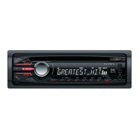
Shows the display format during destination setting.

1-3. Entering the Destination Code

Method for entering the destination code using the main unit.

1-4. Destination Code

Table listing destination codes for various models.

2. Confirmation After Destination Setting

Procedure to verify the correct destination setting.

Service Notes

Test Discs

Lists test discs for confirming operation.

Servo Board Replacement

Recommends replacing the entire servo board.

Sensor Board Replacement

Recommends exchanging the mechanical block.

Lithium Battery Replacement (Remote)

Guide for replacing the remote commander's battery.

USB Connector and AUX Jack Replacement

Replacement Procedure

Steps for replacing USB connector and AUX jack, requiring alignment.

Cleaning Connectors

Cleaning Procedure

Steps to clean connectors between unit and front panel.

Extension Cable and Service Position

Service Connection

Diagram showing how to connect the jig cable for servicing.

SECTION 2 GENERAL

Cautions

Unit power, wiring precautions, and eye hazard warning.

Connection Diagram (3)

Illustrates various connection examples for power and speakers.

Installation Procedures

Precautions

Guidelines for choosing location and ensuring secure installation.

Mounting Angle Adjustment

Recommendation to adjust mounting angle to less than 45°.

Removing Protection Collar and Bracket

Steps to remove the protection collar and bracket.

Mounting Example (5)

Example of installing the unit into a dashboard.

Mounting in Japanese Car (6)

Note about potential installation issues in Japanese cars.

Detaching and Attaching Front Panel (7)

Instructions for removing and reattaching the front panel.

Warning: No ACC Position

Advice on setting Auto Off function if car lacks ACC position.

Fuse Replacement (8)

Guidance on replacing the fuse with the correct amperage.

Precautions for AEP and UK Models

General Precautions

General warnings for operating the unit.

Example of Connections

Shows connection examples.

Connection Diagram (3)

Wiring diagram for connecting the unit.

Installation Procedures (Multilingual)

Precautions

Guidelines for installation location and secure mounting.

Mounting Angle Adjustment

Recommendation to adjust mounting angle.

Removing Protection Collar and Bracket

Steps to remove collar and bracket.

Mounting Example

Example of installing the unit.

Detaching and Attaching Front Panel

Instructions for removing and reattaching the front panel.

Warning: No ACC Position

Advice on setting Auto Off function.

Fuse Replacement

Guidance on replacing the fuse.

Power Connection Diagram

Diagram for power connections.

SECTION 4 DIAGRAMS

4-1. Block Diagram - Servo Section

Block diagram of the servo section and CD mechanism.

Installation Procedures (Multilingual)

Precautions

Guidelines for installation location and secure mounting.

Mounting Angle Adjustment

Recommendation to adjust mounting angle.

Removing Protection Collar and Bracket

Steps to remove collar and bracket.

Mounting Example

Example of installing the unit.

Detaching and Attaching Front Panel

Instructions for removing and reattaching the front panel.

Warning: No ACC Position

Advice on setting Auto Off function.

Fuse Replacement

Guidance on replacing the fuse.

Power Connection Diagram

Diagram for power connections.

Cautions (E, Mexican, Indian Models)

General Precautions

Unit power, wiring precautions, and eye hazard warning.

Connection Example (2)

Shows subwoofer direct connection example.

Connection Diagram (3)

Illustrates various connection examples.

Installation Procedures (Spanish)

Precautions

Guidelines for installation location and secure mounting.

Mounting Angle Adjustment

Recommendation to adjust mounting angle.

Removing Protection Collar and Bracket

Steps to remove collar and bracket.

Mounting Example (5)

Example of installing the unit.

Mounting in Japanese Car (6)

Note about potential installation issues.

Note on Screws

Advice to use supplied screws for installation.

Detaching and Attaching Front Panel (7)

Instructions for removing and reattaching the front panel.

Warning: No ACC Position

Advice on setting Auto Off function.

Fuse Replacement (8)

Guidance on replacing the fuse.

Notes on Tuning Step

Information on setting the tuning step.

Cautions (Saudi Arabia Model)

General Precautions

Unit power, wiring precautions, and eye hazard warning.

Connection Example (2)

Shows subwoofer direct connection example.

Connection Diagram (3)

Illustrates various connection examples.

Installation Procedures (Arabic/Persian)

Precautions

Guidelines for installation location and secure mounting.

Mounting Angle Adjustment

Recommendation to adjust mounting angle.

Removing Protection Collar and Bracket

Steps to remove collar and bracket.

Mounting Example (5)

Example of installing the unit.

Mounting in Japanese Car (6)

Note about potential installation issues.

How to Detach and Attach Front Panel (7)

Instructions for removing and reattaching the front panel.

Warning: No ACC Position

Advice on setting Auto Off function.

Fuse Replacement (8)

Guidance on replacing the fuse.

Cautions (Argentina Model)

General Precautions

Unit power, wiring precautions, and eye hazard warning.

Connection Example (2)

Shows subwoofer direct connection example.

Connection Diagram (3)

Illustrates various connection examples.

Installation Procedures (Spanish)

Precautions

Guidelines for installation location and secure mounting.

Mounting Angle Adjustment

Recommendation to adjust mounting angle.

Removing Protection Collar and Bracket

Steps to remove collar and bracket.

Mounting Example (5)

Example of installing the unit.

Mounting in Japanese Car (6)

Note about potential installation issues.

How to Detach and Attach Front Panel (7)

Instructions for removing and reattaching the front panel.

Warning: No ACC Position

Advice on setting Auto Off function.

Fuse Replacement (8)

Guidance on replacing the fuse.

Power Connection Diagram (9)

Diagram for power connections.

Cautions (Korean Model)

General Precautions

Unit power, wiring precautions, and eye hazard warning.

Connection Diagram (3)

Illustrates various connection examples.

Installation Procedures (Korean)

Precautions

Guidelines for installation location and secure mounting.

Mounting Angle Adjustment

Recommendation to adjust mounting angle.

Removing Protection Collar and Bracket

Steps to remove collar and bracket.

Mounting Example (5)

Example of installing the unit.

Mounting in Japanese Car (6)

Note about potential installation issues.

Detaching and Attaching Front Panel (7)

Instructions for removing and reattaching the front panel.

Warning: No ACC Position

Advice on setting Auto Off function.

Fuse Replacement (8)

Guidance on replacing the fuse.

SECTION 3 DISASSEMBLY

3-1. Disassembly Flow

Flowchart showing the order of disassembly.

3-2. Mini Fuse (Blade Type) and Cover

Instructions for removing the mini fuse and cover.

3-3. Sub Panel Block Removal

3-4. CD Mechanism Deck Removal

3-5. Main Board Removal

3-6. Servo Board Removal

3-7. Chassis (T) Sub Assy Removal

3-8. Roller Arm Assy Removal

3-9. Chassis (OP) Assy Removal

3-10. Chucking Arm Sub Assy Removal

3-11. Sled Motor Assy Removal

3-12. Optical Pick-Up Section Removal

3-13. Optical Pick-Up Assembly Notes

SECTION 4 DIAGRAMS

4-1. Block Diagram - Servo Section

Block diagram of the servo section and CD mechanism.

4-2. Block Diagram - Main Section

4-3. Block Diagram - Panel, Power Supply Section

Notes on Diagrams

Notes for Printed Wiring Boards

Notes on interpreting printed wiring boards.

Notes for Schematic Diagrams

Notes on interpreting schematic diagrams.

Waveforms

Examples of waveforms for key ICs.

4-4. Schematic Diagram - Main Section (1/5)

4-5. Schematic Diagram - Main Section (2/5)

4-6. Schematic Diagram - Main Section (3/5)

4-7. Schematic Diagram - Main Section (4/5)

4-8. Schematic Diagram - Main Section (5/5)

4-9. Printed Wiring Board - Main Section (1/2) (Except Saudi Arabia model)

4-10. Printed Wiring Boards - Main Section (2/2) (Except Saudi Arabia model)

4-11. Printed Wiring Board - Main Section (1/2) (Saudi Arabia model)

4-12. Printed Wiring Boards - Main Section (2/2) (Saudi Arabia model)

4-13. Printed Wiring Board - Key Board

4-14. Schematic Diagram - Key Board

IC Block Diagrams

MAIN Board - IC301 TDF8556AJ/N5

Block diagram for IC301.

IC401 BD3467FV-E2

Block diagram for IC401.

IC402 MM1836A33NRE

Block diagram for IC402.

IC603 BU33TD3WG-TR

Block diagram for IC603.

IC681, 682 BU15TD3WG-TR

Block diagrams for IC681 and IC682.

IC Block Diagrams (Continued)

IC1300 OZ539IGN-A1-0-TR

Block diagram for IC1300.

KEY Board - IC901 PT16512-LQ

Block diagram for IC901 on the key board.

IC Pin Function Description: IC501 (Main System Controller)

IC501 Pin No. 1-15

Pin descriptions for IC501 (1-15).

IC501 Pin No. 16-38

Pin descriptions for IC501 (16-38).

IC501 Pin No. 39-60

Pin descriptions for IC501 (39-60).

IC Pin Function Description: IC501 (Continued)

IC501 Pin No. 61-75

Pin descriptions for IC501 (61-75).

IC501 Pin No. 76-100

Pin descriptions for IC501 (76-100).

IC Pin Function Description: IC601 (Sub System Controller)

IC601 Pin No. 1-36

Pin descriptions for IC601 (1-36).

IC Pin Function Description: IC601 (Continued)

IC601 Pin No. 61-144

Pin descriptions for IC601 (61-144).

IC Pin Function Description: IC701 (CD Head Amp, DSP)

IC701 Pin No. 1-36

Pin descriptions for IC701 (1-36).

IC Pin Function Description: IC701 (Continued)

IC701 Pin No. 69-100

Pin descriptions for IC701 (69-100).

SECTION 5 EXPLODED VIEWS

5-1. Main Section

Exploded view of the main section.

5-2. Front Panel Section

5-3. CD Mechanism Deck Section

SECTION 6 ELECTRICAL PARTS LIST

Key Board Parts List

Electrical parts list for the key board.

Key Board Parts List (Continued)

LED Parts List

List of LEDs with part numbers and descriptions.

Transistor Parts List

List of transistors with part numbers.

Resistor Parts List

List of resistors with part numbers.

Key Board Parts List (Continued)

Resistor List (R935-R963)

Continued list of resistors with part numbers.

Resistor List (R949-R963)

Continued list of resistors with part numbers.

Key Board Parts List (Continued)

Resistor List (R963-R975)

Continued list of resistors with part numbers.

Capacitor List (C10-C439)

List of capacitors with part numbers.

Main Board Parts List

Capacitor List (C440-C798)

Continued list of capacitors with part numbers.

Main Board Parts List (Continued)

Capacitor List (C802-C1320)

Continued list of capacitors with part numbers.

IC List

List of integrated circuits with part numbers.

Jack List

List of jacks with part numbers.

Coil List

List of coils with part numbers.

Transistor List

List of transistors with part numbers.

Main Board Parts List (Continued)

Resistor List (R302-R595)

List of resistors with part numbers.

Main, Sensor, Servo Parts List

Resistor List (R601-R751)

List of resistors with part numbers.

Resistor List (R763-R1320)

List of resistors with part numbers.

Vibrator List

List of vibrator components.

Sensor Board Notes

Note on servo board and sensor board replacement.

Parts for Installation and Connections

Miscellaneous Parts

Lists miscellaneous parts like boards and connectors.

Front Panel Parts

Lists various front panel assemblies and parts.

Accessories

Lists included accessories like remote commander and manuals.

Parts for Installation and Connections (Continued)

Fitting Frame Assembly

Exploded view of fitting frame assembly.

Key (Frame)

Exploded view of frame keys.

Collar (1DIN)

Exploded view of 1DIN collars.

Connection Cables

Exploded view of connection cables.

Antenna Adapter

Exploded view of antenna adapter.

Bushing and Fitting Screws

Exploded view of bushings and fitting screws.

Revision History

Related product manuals