EasyManua.ls Logo

Sony CDX-GT20W User Manual

Sony CDX-GT20W
48 pages
To Next Page IconTo Next Page
Page #1 background imageLoading...
Page #1 background image
1
Ver. 1.0 2005. 09
Model Name Using Similar Mechanism NEW
CD Drive Mechanism Type MG-611WA-186//C
Optical Pick-up Name KSS1000E
SERVICE MANUAL
US Model
Canadian Model
CDX-GT20W/GT200
AEP Model
UK Model
CDX-GT200/GT200E/GT200S
E Model
CDX-GT250S
CDX-GT20W/GT200/GT200E/
GT200S/GT250S
SPECIFICATIONS
• The tuner and CD sections have no adjustments.
Sony Corporation
e Vehicle Group
Published by Sony Engineering Corporation
9-879-862-01
2005I04-1
© 2005. 09
FM/MW/LW COMPACT DISC PLAYER
CDX-GT200: AEP,UK/GT200E/GT200S
FM/AM COMPACT DISC PLAYER
CDX-GT20W/GT200: US,CND/GT250S
AUDIO POWER SPECIFICATIONS (US MODEL)
POWER OUTPUT AND TOTAL HARMONIC DISTORTION
23.2 watts per channel minimum continuous average power into
4 ohms, 4 channels driven from 20 Hz to 20 kHz with no more
than 5% total harmonic distortion.
CD Player section
Signal-to-noise ratio: 120 dB
Frequency response: 10 – 20,000 Hz
Wow and flutter: Below measurable limit
Tuner section
FM
Tuning range: CDX-GT20W/GT200 (US, Canadian):
87.5 – 107.9 MHz
CDX-GT200 (AEP, UK)/GT200E/GT200S:
87.5 – 108.0 MHz
CDX-GT250S:
87.5 – 108.0 MHz (at 50 kHz step)
87.5 – 107.9 MHz (at 200 kHz step)
FM tuning interval (CDX-GT250S only):
50 kHz/200 kHz switchable
Antenna terminal: External antenna connector
Intermediate frequency: 10.7 MHz/450 kHz
Usable sensitivity: 9 dBf
Selectivity: 75 dB at 400 kHz
Signal-to-noise ratio: 67 dB (stereo), 69 dB (mono)
Harmonic distortion at 1 kHz:
0.5 % (stereo), 0.3 % (mono)
Separation: 35 dB at 1 kHz
Frequency response: 30 – 15,000 Hz
AM (CDX-GT20W/GT200 (US, Canadian)/GT250S)
Tuning range: CDX-GT20W/GT200 (US, Canadian):
530 – 1,710 kHz
CDX-GT250S:
531 – 1,602 kHz (at 9 kHz step)
530 – 1,710 kHz (at 10 kHz step)
AM tuning interval (CDX-GT250S only):
9 kHz/10 kHz switchable
Antenna terminal: External antenna connector
Intermediate frequency: 10.7 MHz/450 kHz
Sensitivity: 30 µV
MW/LW (CDX-GT200 (AEP, UK)/GT200E/GT200S)
Tuning range: MW: 531 – 1,602 kHz
LW: 153 – 279 kHz
Aerial terminal: External aerial connector
Intermediate frequency: 10.7 MHz/450 kHz
Sensitivity: MW: 30 µV, LW: 40 µV
Power amplifier section
Outputs: Speaker outputs (sure seal connectors)
Speaker impedance: 4 – 8 ohms
Maximum power output: CDX-GT20W/GT200 (US, Canadian)/GT250S:
52 W × 4 (at 4 ohms)
CDX-GT200 (AEP, UK)/GT200E/GT200S:
50 W × 4 (at 4 ohms)
– Continued on next page –
Question and Answer IconNeed help?

Do you have a question about the Sony CDX-GT20W and is the answer not in the manual?

Sony CDX-GT20W Specifications

General IconGeneral
BrandSony
ModelCDX-GT20W
CategoryCar Receiver
LanguageEnglish

Summary

Technical Specifications

Audio Power Output

Details the minimum continuous average power output and total harmonic distortion.

CD Player Specifications

Lists signal-to-noise ratio, frequency response, and wow and flutter for the CD player.

Tuner Section Specifications

Covers FM and AM tuning ranges, intermediate frequencies, sensitivity, and selectivity.

Power Amplifier Specifications

Specifies speaker impedance and maximum power output.

General Information and Safety

Safety Precautions and Handling

Covers handling of optical pick-up, laser diode, and critical safety components.

Control Layout and Operation

US and Canadian Models Controls

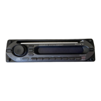
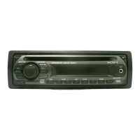
Identifies and explains the controls on the main unit for US/Canadian models.

AEP, UK, and GT200S Models Controls

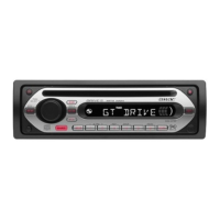
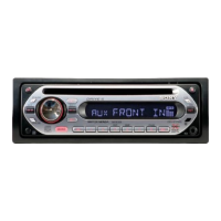
Identifies and explains the controls on the main unit for AEP/UK/GT200S models.

GT200E Model Controls

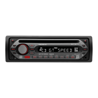
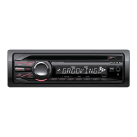
Identifies and explains the controls on the main unit for the GT200E model.

GT250S Model Controls

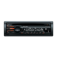
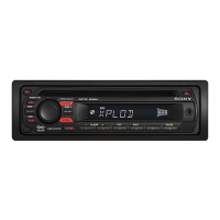
Identifies and explains the controls on the main unit for the GT250S model.

Connections and Wiring

Connection Diagram

Illustrates the wiring for audio output, power antenna, and amplifier remote connections.

Connection Notes and Warnings

Provides important notes regarding power, antenna, and speaker connections for safe operation.

Disassembly Procedure

Disassembly Sequence Overview

Outlines the step-by-step process for disassembling the unit.

Diagrams

CD Section Block Diagram

Shows the functional blocks and signal paths within the CD playback section.

Main Section Block Diagram

Illustrates the main functional blocks and signal flow of the unit.

CD Mechanism Schematic Diagram (Part 1)

Provides a detailed schematic for the CD mechanism's servo and control circuitry.

CD Mechanism Schematic Diagram (Part 2)

Provides a detailed schematic for the CD mechanism's driver and interface circuitry.

Main Section Schematic Diagram (Part 1)

Details the schematic for the tuner, AUX buffer, and initial volume control stages.

Main Section Schematic Diagram (Part 2)

Details the schematic for the main power amplifier and control logic.

Main Section Schematic Diagram (Part 3)

Details the schematic for the I2C bus, RDS, and other interface circuits.

Diagram Notes and Waveforms

Integrated Circuit Block Diagrams

IC Pin Descriptions

Related product manuals