Do you have a question about the Sony CDX-GT200S and is the answer not in the manual?
Details audio output, harmonic distortion, CD player performance, tuner sensitivity, and amplifier output power.
Covers service procedures, handling optical components, laser emission safety, chip replacement, and safety warnings.
Details playable disc formats, extension cable usage for servicing, and unleaded solder guidelines.
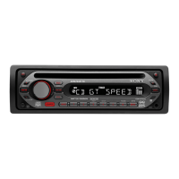
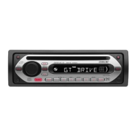
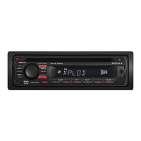
Describes main unit and remote controls for specific model groups on the US/Canadian and AEP/UK/GT200S series.
Details the buttons and functions for the CDX-GT250S main unit and its remote commander.
Illustrates wiring connections and provides important notes on antenna, amplifier, and speaker connections.
Provides the connection diagram for AEP/UK/GT200E/GT200S models and lists important warnings.
Outlines the step-by-step procedure for disassembling the unit, referencing specific component pages.
Details the steps for removing the sub panel and the CD mechanism block, including screw and claw locations.
Details the steps for removing the sub panel and the CD mechanism block, including screw and claw locations.
Explains how to remove the main board and the chassis (T) sub assembly, indicating screw and claw points.
Explains how to remove the main board and the chassis (T) sub assembly, indicating screw and claw points.
Details the steps for removing the roller arm assembly and the chassis (OP) assembly, identifying springs and gears.
Details the steps for removing the roller arm assembly and the chassis (OP) assembly, identifying springs and gears.
Covers the removal of the optical pick-up and the SL motor assembly (M902), including associated screws and shafts.
Covers the removal of the optical pick-up and the SL motor assembly (M902), including associated screws and shafts.
Explains the disassembly of the LE motor assembly (M903) and the servo board, noting solder points and screws.
Explains the disassembly of the LE motor assembly (M903) and the servo board, noting solder points and screws.
Provides the block diagram for the CD section and shows the physical location of the unit's circuit boards.
Provides the block diagram for the CD section and shows the physical location of the unit's circuit boards.
Illustrates the signal flow and component interconnections within the main section of the unit.
Shows the block diagram for the display section and the location of the key and jack boards.
Shows the block diagram for the display section and the location of the key and jack boards.
Offers guidelines for understanding diagrams and presents measured waveforms for key components.
Offers guidelines for understanding diagrams and presents measured waveforms for key components.
Shows the physical layout of the CD mechanism's servo and sensor boards, detailing component placement.
Shows the physical layout of the CD mechanism's servo and sensor boards, detailing component placement.
Shows the physical layout of the CD mechanism's servo and sensor boards, detailing component placement.
Presents the first part of the schematic diagram for the servo board within the CD mechanism.
Continues the servo board schematic and shows connection points to the main board for the CD mechanism.
Continues the servo board schematic and shows connection points to the main board for the CD mechanism.
Illustrates the physical layout of components on the main board.
Shows the schematic for the tuner unit, volume control, RDS demodulator, and AUX buffer sections.
Shows the schematic for the tuner unit, volume control, RDS demodulator, and AUX buffer sections.
Details the schematic for the controlled power amplifier and related control circuits on the main board.
Presents the schematic for the system control IC and I2C bus communication circuitry on the main board.
Illustrates the component placement on the key and jack boards.
Illustrates the component placement on the key and jack boards.
Shows the schematic for the key matrix, system control interface, and remote control receiver.
Shows the schematic for the key matrix, system control interface, and remote control receiver.
Provides simplified block diagrams for integrated circuits used on the servo and main boards.
Illustrates the internal structure and pin-out functions of the TDA8588BJ IC used in the power amplifier section.
Lists and describes the functions of pins for the IC3 (MB90486BPFV-G-158E1) CD System Control IC.
Continues the list and description of pins for the IC3 CD System Control IC.
Lists and describes the functions of pins for the IC501 (MB90487APF-G-155E1) System Control IC.
Continues the list and description of pins for the IC501 System Control IC.
Shows an exploded view of the main section of the unit, identifying all parts and their reference numbers.
Illustrates the exploded view of the front panel, detailing components like buttons, display, and key board.
Shows the exploded view of the CD mechanism's chassis, servo board, and springs.
Details the exploded view of the CD mechanism, including the optical pick-up and motor assemblies.
Details the exploded view of the CD mechanism, including the optical pick-up and motor assemblies.
Presents an exploded view of the CD mechanism, focusing on roller arm, gears, and springs.
Shows the final part of the CD mechanism's exploded view, detailing gears and levers.
Lists electrical parts for jacks, key board switches, LEDs, and ICs.
Lists electrical parts for jacks, key board switches, LEDs, and ICs.
Lists electrical parts for key switches, transistors, and resistors used in the key section.
Lists electrical parts for key switches, transistors, and resistors used in the key section.
Lists resistors and capacitors for the main section of the unit.
Lists resistors and capacitors for the main section of the unit.
Lists capacitors, connectors, and diodes for the main, sensor, and servo sections.
Lists capacitors, connectors, and diodes for the main, sensor, and servo sections.
Lists inductors, ICs, jacks, transistors, and resistors for the main section.
Lists inductors, ICs, jacks, transistors, and resistors for the main section.
Lists a wide range of resistors used in the main section.
Lists resistors, switches, tuner unit, and vibrator components.
Lists resistors, switches, tuner unit, and vibrator components.
Lists resistors, switches, oscillator, and connector parts for the servo section.
Lists resistors, switches, oscillator, and connector parts for the servo section.
Lists all accessories included with the unit, such as remote commander, manuals, and installation hardware.
Lists all accessories included with the unit, such as remote commander, manuals, and installation hardware.
| Audio system | 30 |
|---|---|
| MP3 playback | Yes |
| Tuner type | SSIR-EXA |
| FM band range | 87 - 108 MHz |
| Ready for iPod | No |
| Frequency range | 10 - 20000 Hz |
| Equalizer bands quantity | 3 |
| Signal-to-Noise Ratio (SNR) | 120 dB |
| Filtering description | 8 fs |
| Key illumination color | Red |
| Dimensions (WxDxH) | 178 x 179 x 50 mm |
|---|