Do you have a question about the Sony CDX-GT282S and is the answer not in the manual?
Details on signal-to-noise ratio, frequency response, and wow/flutter.
FM tuning range, interval, sensitivity, selectivity, and frequency response.
AM/MW/SW tuning range, interval, sensitivity, selectivity, and frequency response.
Details on speaker outputs, impedance, and maximum power output.
Includes audio outputs, inputs, tone controls, and power requirements.
Guidelines for safe handling of the optical pick-up block and base unit.
Instructions and safety precautions for checking laser diode emission.
Important notes and cautions for replacing chip components.
Recommended test discs and information on CD playback compatibility.
Critical warning regarding components identified with a mark for safety.
Describes the characteristics of unleaded solder and its properties.
Instructions for connecting the jig (extension cable) for servicing.
Procedure and alignment notes for replacing the AUX jack.
Guidance on replacing the complete Servo Board.
Precautions for cleaning and handling the 15-pin connector.
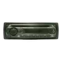
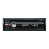
Overview of controls and basic operations for specific models.
Overview of controls and basic operations for specific models.
Procedure for disassembling the sub panel assembly.
Procedure for disassembling the CD mechanism block.
Procedure for accessing and removing the main board.
Procedure for accessing and removing the servo board.
Procedure for disassembling the chassis (T) sub assembly.
Procedure for disassembling the roller arm assembly.
Procedure for disassembling the chassis (OP) assembly.
Procedure for disassembling the chucking arm sub assembly.
Procedure for disassembling the sled motor assembly.
Procedure for disassembling the optical pick-up section.
Procedure for disassembling the optical pick-up.
Block diagram of the main unit's functional sections.
Block diagram of the unit's display section.
Layout of the main section's printed wiring board.
Detailed schematic diagram for the main section, part 1.
Detailed schematic diagram for the main section, part 2.
Detailed schematic diagram for the main section, part 3.
Layout of the key section's printed wiring board.
Detailed schematic diagram for the key section.
Visual breakdown of the main section's components.
Visual breakdown of the front panel section's components.
Visual breakdown of the CD mechanism section's components.
| Brand | Sony |
|---|---|
| Model | CDX-GT282S |
| Category | Car Receiver |
| Language | English |