Do you have a question about the Sony CDX-GT39UE and is the answer not in the manual?
Details specifications for FM, AM, MW/LW tuning ranges, sensitivity, and frequency response.
Lists signal-to-noise ratio and frequency response for the CD player.
Specifies the USB interface type and maximum current.
Outlines speaker outputs, impedance, and maximum power output.
Describes the connection of a jig for servicing and repair procedures.
Procedure for disassembling the sub panel.
Steps to remove the CD mechanism block.
Instructions for accessing and removing the main board.
Guide for disassembling and removing the servo board.
Procedure for disassembling the chassis (T) sub assembly.
Steps for removing the roller arm assembly.
Instructions for disassembling the chassis (OP) assembly.
Procedure for removing the chucking arm sub assembly.
Steps to disassemble and remove the sled motor assembly.
Guide for disassembling the optical pick-up section.
Detailed steps for removing the optical pick-up unit.
Illustrates main functional blocks and signal flow.
Shows block diagram for display and control functions.
Depicts layout of components and traces on the main board.
Provides the first part of the main section's circuit schematic.
Details the circuit schematic for the key and jack boards.
Visual representations of integrated circuit functions and pin assignments.
Exploded diagram showing main section components and assembly.
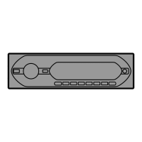
Exploded view of the front panel assembly and its parts.
Exploded diagram of the CD mechanism unit and its components.
Lists electrical components for the key board.
Details electrical parts for the main board.
Lists accessories and installation parts.
| Power Output | 52 W x 4 |
|---|---|
| RMS Power Output | 17 W x 4 |
| Tuner | FM/AM |
| Preset Stations | 30 |
| CD Playback | Yes |
| MP3 Playback | Yes |
| WMA Playback | Yes |
| USB Port | Yes |
| Bluetooth | No |
| Display | LCD |
| Equalizer | Yes |
| Equalizer Bands | 5 |
| AUX Input | Yes |
| Audio Output Channels | 4 |
| Removable Front Panel | Yes |
| Product Colour | Black |
| Remote Control | Yes |
| Steering Wheel Control | Yes |