EasyManua.ls Logo

Sony CDX-GT41UW User Manual

Sony CDX-GT41UW
46 pages
To Next Page IconTo Next Page
Page #1 background imageLoading...
Page #1 background image
SERVICE MANUAL
Sony Corporation
eVehicle Division
Published by Sony Techno Create Corporation
US Model
Canadian Model
CDX-GT41UW/GT410U
E Model
CDX-GT460U/GT460US
Chinese Model
CDX-GT460U
9-887-470-03
2007C04-1
© 2007.03
Ver. 1.2 2007.03
SPECIFICATIONS
CD player section
Signal-to-noise ratio 120 dB
Frequency response 10 – 20,000 Hz
Wow and flutter Below measurable limit
Tuner section
FM
Tuning range GT41UW/GT410U:
87.5 – 107.9 MHz
GT460U/GT460US:
87.5 – 108.0 MHz (at 50 kHz step)
87.5 – 107.9 MHz (at 200 kHz step)
FM tuning interval GT460U/GT460US:
50 kHz/200 kHz switchable
Antenna terminal External antenna connector
Intermediate frequency 10.7 MHz/450 kHz
Usable sensitivity 9 dBf
Selectivity 75 dB at 400 kHz
Signal-to-noise ratio 67 dB (stereo), 69 dB (mono)
Harmonic distortion at 1 kHz
0.5% (stereo), 0.3% (mono)
Separation 35 dB at 1 kHz
Frequency response 30 – 15,000 Hz
AM
Tuning range GT41UW/GT410U:
530 – 1,710 kHz
GT460U/GT460US:
531 – 1,602 kHz (at 9 kHz step)
530 – 1,710 kHz (at 10 kHz step)
AM tuning interval GT460U/GT460US:
9 kHz/10 kHz switchable
Antenna terminal External antenna connector
Intermediate frequency 10.7 MHz/450 kHz
Sensitivity 30 µV
USB player section
Interface USB (Full-speed)
Maximum current 500 mA
Power amplifier section
Outputs Speaker outputs (sure seal connectors)
Speaker impedance 4 – 8 ohms
Maximum power output
52 W × 4 (at 4 ohms)
The tuner and CD sections have no adjustments.
Model Name Using Similar Mechanism NEW
CD Drive Mechanism Type MG-101U-188//Q
Optical Pick-up Name DAX-25A
– Continued on next page –
CDX-GT41UW/GT410U/
GT460U/GT460US
FM/AM COMPACT DISC PLAYER
(Photo: CDX-GT460U)
AUDIO POWER SPECIFICATIONS (US MODEL)
POWER OUTPUT AND TOTAL HARMONIC DISTORTION
23.2 watts per channel minimum continuous average power into
4 ohms, 4 channels driven from 20 Hz to 20 kHz with no more
than 5% total harmonic distortion.
Question and Answer IconNeed help?

Do you have a question about the Sony CDX-GT41UW and is the answer not in the manual?

Sony CDX-GT41UW Specifications

General IconGeneral
BrandSony
ModelCDX-GT41UW
CategoryCar Receiver
LanguageEnglish

Summary

Specifications

CD Player Specifications

Technical details of the CD playback capabilities.

Tuner Specifications

Technical details of the FM/AM radio tuner.

USB Player Specifications

Technical details of the USB playback functionality.

Power Amplifier Specifications

Technical details of the internal power amplifier.

Audio Power Specifications (US Model)

General Specifications

Outputs and Inputs

Description of the device's output and input terminals.

Tone Controls

Details on the bass, mid, and treble control ranges.

Power, Dimensions, and Mass

Power requirements, physical dimensions, and weight.

Supplied Accessories

List of items included in the package.

Test Discs

Service Notes

Handling Optical Pick-up

Precautions for handling the optical pick-up block.

Laser Diode Emission Check

Guidelines for checking the laser diode emission safely.

Extension Cable and Service Position

Section 1 General

Location of Controls

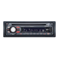
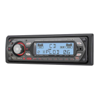
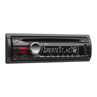
Identification and location of the unit's controls.

Connections Overview

Explanation of the unit's connection terminals.

Connections

Section 2 Disassembly

Sub Panel (FL-U) Assy

Procedure for removing the sub panel (FL-U) assembly.

CD Mechanism Block

Procedure for removing the CD mechanism block.

Main Board

Procedure for removing the main board.

Servo Board

Procedure for removing the servo board.

Chassis (T) Sub Assy

Procedure for removing the chassis (T) sub assembly.

Roller Arm Assy

Procedure for removing the roller arm assembly.

Chassis (OP) Assy

Procedure for removing the chassis (OP) assembly.

Section 3 Diagnosis Function

Reset Count Display

Displays the count of reset operations.

Watchdog Timer Reset Count

Shows reset count based on watchdog timer.

Connected Units Display

Displays the number of connected units.

Operating Hours Display

Shows the total operating hours of the device.

CD Error Information Display

Details on CD errors, disc types, and operating hours.

Offset/Failure Error Display

Displays offset and failure error history.

USB Error Information and Disc Details

Shows disc type and operating hours for USB errors.

Section 4 Diagrams

Block Diagram - Main Section

Block diagram of the main section of the unit.

Block Diagram - Display Section

Block diagram of the display section of the unit.

Waveforms

Graphical representations of signal waveforms.

Printed Wiring Board - Main Section

Printed wiring board layout for the main section.

Schematic Diagram - Main Section (1/3)

Schematic diagram of the main section (part 1 of 3).

Schematic Diagram - Main Section (2/3)

Schematic diagram of the main section (part 2 of 3).

Schematic Diagram - Main Section (3/3)

Schematic diagram of the main section (part 3 of 3).

Printed Wiring Board - Key Section

Printed wiring board layout for the key section.

Schematic Diagram - Key Section

Schematic diagram of the key section.

IC Block Diagrams

Block diagrams for integrated circuits used in the unit.

IC Pin Description

Section 5 Exploded Views

Main Section Exploded View

Exploded view of the main section of the unit.

Front Panel Section Exploded View

Exploded view of the front panel assembly.

CD Mechanism Section Exploded View

Exploded view of the CD mechanism section.

Revision History

Related product manuals