Do you have a question about the Sony CDX-GT44IP and is the answer not in the manual?
Details on audio power, CD player, and tuner performance metrics.
Technical data for the CD playback section, including signal-to-noise ratio and frequency response.
Performance data for FM and AM/MW/LW tuning, sensitivity, and distortion.
Precautions for preventing electrostatic breakdown and handling the flexible board.
Safety guidelines for checking the laser diode emission, emphasizing safe observation distance.
Identifies critical components vital for safe operation, requiring specific replacement parts.
Step-by-step guide for removing the sub panel assembly.
Procedure for detaching the CD mechanism block from the unit.
Instructions for safely removing the main circuit board.
Steps for disassembling and removing the servo board.
Detailed instructions for disassembling the optical pick-up section.
Procedure to enter and set the diagnosis display mode using unit buttons or remote.
How to exit the diagnosis function mode by pressing the OFF button.
The default display shown upon entering the diagnosis mode.
Displays the reset count in hexadecimal format.
Shows the total operating hours of the unit in hexadecimal format.
Details various CD error codes and their descriptions.
Indicates offset or failure errors with history tracking.
High-level block diagram illustrating the main functional sections and signal flow.
Layout of components and connections on the main circuit board.
Detailed schematic of the main section, part one of four.
Internal block diagrams for key integrated circuits used in the unit.
Visual breakdown of the main unit components with part numbers.
Detailed exploded diagram of the front panel assembly and its parts.
Exploded view of the CD mechanism (MG-101TC-188//C) and associated parts.
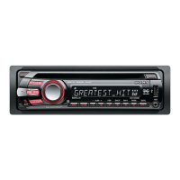
| MP3 playback | Yes |
|---|---|
| Tuner type | SSIR-EXA |
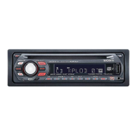
| Product color | Black |
| Equalizer bands quantity | 3 |
| Signal-to-Noise Ratio (SNR) | 120 dB |
| File type | WMA, MP3 |
| Key illumination color | Red |
| Dimensions (WxDxH) | 178 x 179 x 50 mm |
|---|