EasyManua.ls Logo

Sony CDX-GT616U User Manual

Sony CDX-GT616U
48 pages
To Next Page IconTo Next Page
Page #1 background imageLoading...
Page #1 background image
SERVICE MANUAL
Sony Corporation
eVehicle Division
Published by Sony Techno Create Corporation
AEP Model
UK Model
CDX-GT610U/GT616U
East European Model
CDX-GT617UE
9-887-473-02
2007C04-1
© 2007.03
Ver. 1.1 2007.03
SPECIFICATIONS
CD player section
Signal-to-noise ratio 120 dB
Frequency response 10 – 20,000 Hz
Wow and flutter Below measurable limit
Tuner section
FM
Tuning range CDX-GT610U/GT616U:
87.5 – 108.0 MHz
CDX-GT617UE:
FM1/FM2: 87.5 – 108.0 MHz (at 50 kHz step)
FM3: 65 – 74 MHz (at 30 kHz step)
Antenna terminal External antenna connector
Intermediate frequency 10.7 MHz/450 kHz
Usable sensitivity 9 dBf
Selectivity 75 dB at 400 kHz
Signal-to-noise ratio 67 dB (stereo), 69 dB (mono)
Harmonic distortion at 1 kHz
0.5% (stereo), 0.3% (mono)
Separation 35 dB at 1 kHz
Frequency response 30 – 15,000 Hz
MW/LW
Tuning range MW: 531 – 1,602 kHz
LW: 153 – 279 kHz
Antenna terminal External antenna connector
Intermediate frequency 10.7 MHz/450 kHz
Sensitivity MW: 30 µV, LW: 40 µV
USB player section
Interface USB (Full-speed)
Maximum current 500 mA
Power amplifier section
Outputs Speaker outputs (sure seal connectors)
Speaker impedance 4 – 8 ohms
Maximum power output
50 W × 4 (at 4 ohms)
The tuner and CD sections have no adjustments.
Model Name Using Similar Mechanism CDX-GT410U/GT414U
CD Drive Mechanism Type MG-101U-188//Q
Optical Pick-up Name DAX-25A
– Continued on next page –
CDX-GT610U/GT616U/
GT617UE
FM/MW/LW COMPACT DISC PLAYER
(Photo: CDX-GT610U)
Question and Answer IconNeed help?

Do you have a question about the Sony CDX-GT616U and is the answer not in the manual?

Sony CDX-GT616U Specifications

General IconGeneral
ModelCDX-GT616U
TypeCar Receiver
Channels4
Peak Power Output52 W
CD PlaybackYes
USB InputYes
AUX InputYes
BluetoothNo
Display TypeLCD
EqualizerYes
Steering Wheel Remote ReadyYes
Audio D/A Converter (DAC)24-bit
Display illuminationYes
Removable front panelYes
Tuner BandsAM/FM
Illumination colorRed

Summary

SPECIFICATIONS

SERVICE NOTES

NOTES ON HANDLING THE OPTICAL PICK-UP BLOCK OR BASE UNIT

Precautions for handling the optical pick-up block to prevent electrostatic damage.

NOTES ON LASER DIODE EMISSION CHECK

Safety guidelines for checking laser diode emission.

SAFETY-RELATED COMPONENT WARNING!!

Warning for critical safety components requiring specific replacement parts.

IMPORTANT REPLACEMENT NOTES

SERVO BOARD REPLACEMENT

Instructions for replacing the complete servo board.

USB CONNECTOR REPLACEMENT

Procedure for replacing the USB connector, including alignment.

20-PIN CONNECTOR HANDLING

Precautions for cleaning and handling the 20-pin connector.

SECTION 1 GENERAL

LOCATION OF CONTROLS AND BASIC OPERATIONS

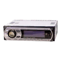
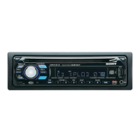
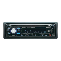
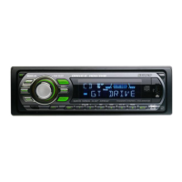
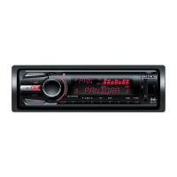
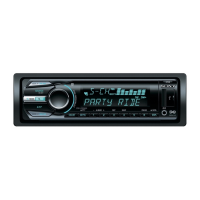
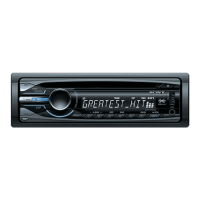
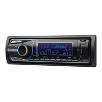
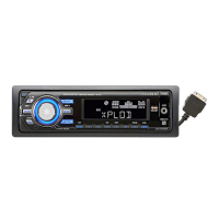
Overview of main unit and remote commander controls and their functions.

SECTION 2 DISASSEMBLY

SUB PANEL ASSY

Steps for disassembling the sub panel assembly.

CD MECHANISM BLOCK

Procedure for removing the CD mechanism block.

MAIN BOARD

Instructions for accessing and removing the main board.

SERVO BOARD

Steps for disassembling the servo board.

CHASSIS (T) SUB ASSY

Procedure for disassembling the chassis (T) sub assembly.

ROLLER ARM ASSY

Steps for disassembling the roller arm assembly.

CHASSIS (OP) ASSY

Procedure for disassembling the chassis (OP) assembly.

SECTION 3 DIAGNOSIS FUNCTION

Setting the Diag display mode

How to enter the diagnostic display mode.

Canceling the Diag display mode

How to exit the diagnostic display mode.

Initial display in the Diag display mode

What is displayed immediately upon entering diagnostic mode.

Reset count display mode

Displays the reset count in hexadecimal format.

Reset count by watchdog timer display mode

Shows reset counts from the watchdog timer.

Number of connected units display mode

Indicates the number of connected units for various components.

Operating hours display mode

Displays the operating hours of the unit.

CD error information display mode

Information related to CD playback errors and disc types.

OFFSET/FAILURE error display mode

Displays offset or failure errors and operating history.

USB error information display mode

Information regarding USB connection errors and history.

SECTION 4 DIAGRAMS

BLOCK DIAGRAM - MAIN SECTION -

Block diagram illustrating the main functional sections of the unit.

BLOCK DIAGRAM - DISPLAY SECTION

Block diagram showing the display and control sections.

PRINTED WIRING BOARD - MAIN SECTION -

Printed wiring board layout for the main section.

SCHEMATIC DIAGRAM - MAIN SECTION (1/3)

First part of the main section schematic diagram.

SCHEMATIC DIAGRAM - MAIN SECTION (2/3)

Second part of the main section schematic diagram.

SCHEMATIC DIAGRAM - MAIN SECTION (3/3)

Third part of the main section schematic diagram.

PRINTED WIRING BOARD - SUB SECTION

Printed wiring board layout for the sub section.

SCHEMATIC DIAGRAM - SUB SECTION

Schematic diagram for the sub section.

PRINTED WIRING BOARD - KEY SECTION

Printed wiring board layout for the key section.

SCHEMATIC DIAGRAM - KEY SECTION

Schematic diagram for the key section.

IC BLOCK DIAGRAMS

IC601 BA8271F-E2 (MAIN Board (1/3))

Block diagram for IC601.

IC401 BD3442FS-E2 (MAIN Board (2/3))

Block diagram for IC401.

IC802 BD9778HFP (MAIN Board (3/3))

Block diagram for IC802.

IC PIN DESCRIPTION

IC501 MB90F046PF-G-102E1 (SYSTEM CONTROL) (MAIN BOARD (3/3))

Pin description for IC501 (System Control).

SECTION 5 EXPLODED VIEWS

MAIN SECTION

Exploded view of the main unit assembly.

FRONT PANEL SECTION

Exploded view of the front panel assembly.

CD MECHANISM SECTION

Exploded view of the CD mechanism section.

SECTION 6 ELECTRICAL PARTS LIST

KEY BOARD

Electrical parts list for the key board.

CAPACITOR

List of capacitors used in the unit.

CONNECTOR

List of connectors used in the unit.

DIODE

List of diodes used in the unit.

JUMPER RESISTOR

List of jumper resistors used in the unit.

SEMICONDUCTORS

List of semiconductor components.

RESISTORS

List of resistors used in the unit.

COILS

List of coils used in the unit.

SWITCH

List of switches used in the unit.

Related product manuals