CDX-GT72W/GT720/GT770
4
SECTION 1
SERVICE NOTE
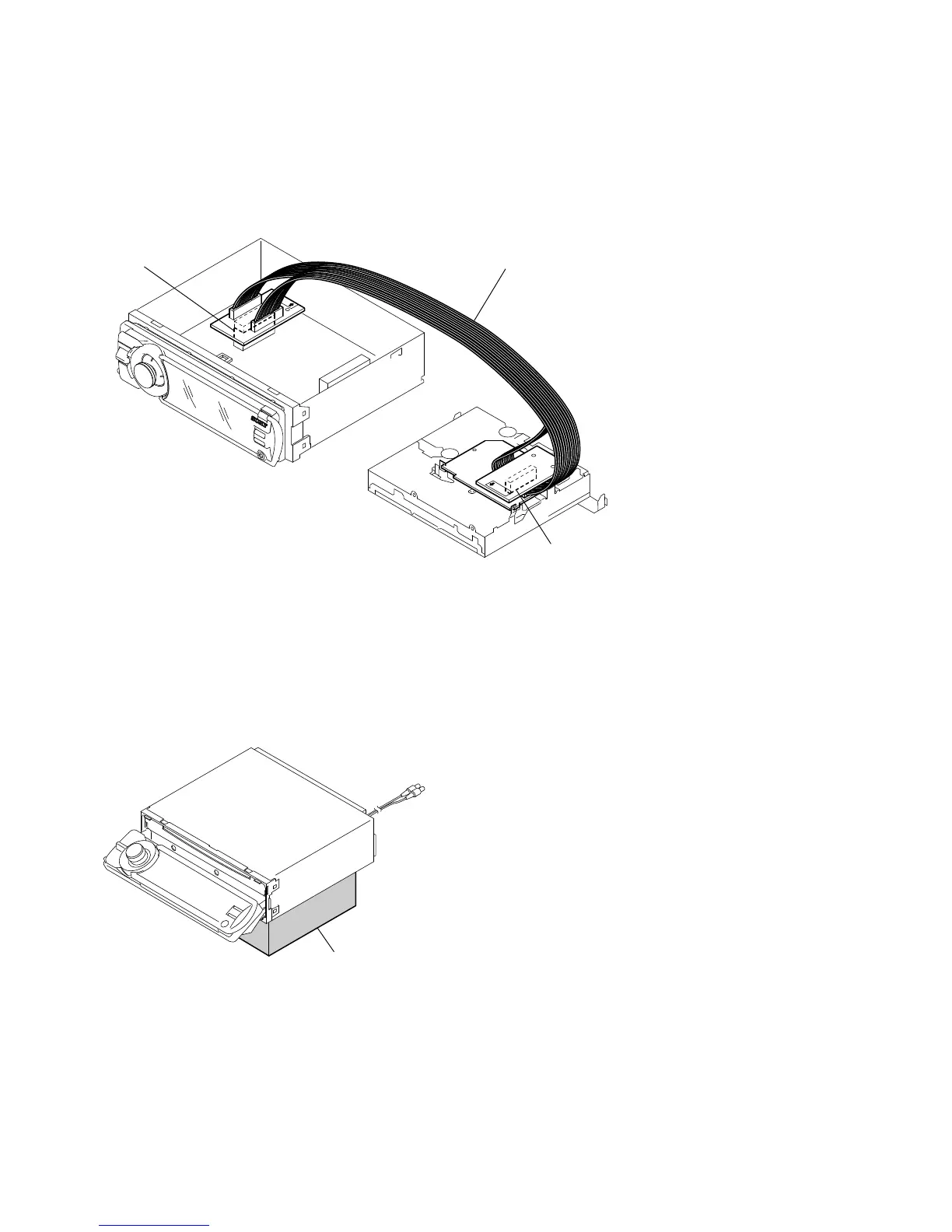
EXTENSION CABLE AND SERVICE POSITION
When repairing or servicing this set, connect the jig (extension
cable) as shown below.
• Connect the MAIN board (CNP301) and the SERVO board
(CN2) with the extension cable (Part No. J-2502-076-1).
NOTE FOR REPLACEMENT OF THE SERVO BOARD
When repairing, the complete SERVO board (A-1177-362-A)
should be replaced since any parts in the SERVO board cannot be
repaired.
NOTE FOR THE OPENING OF THE FRONT PANEL
In this set, the front panel is lowered to below the bottom face
when it is opened.
When servicing the set, place it on a stand having a height of about
2 cm.
SERVO BOARD
CN2
MAIN BOARD
CNP301
J-2502-076-1
stand