Sony Corporation © 2002 Printed in Korea
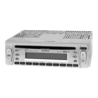
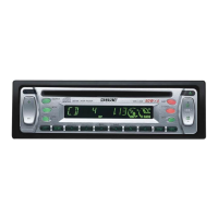
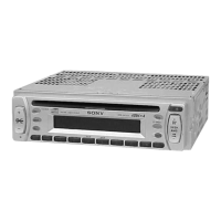
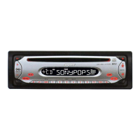
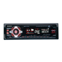
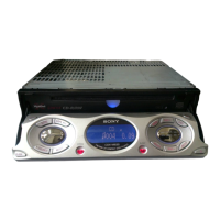
CDX-L300
3-237-525-11 (1)
Parts Iist (1)
The numbers in the list are keyed to those in the
instructions.
Caution
Handle the bracket 1 carefully to avoid injuring
your fingers.
Caut ions
•This unit is designed for negative ground 12 V
DC operation only.
•Do not get the wires under a screw, or caught
in moving parts (e.g. seat railing).
•Before making connections, turn the car
ignition off to avoid short circuits.
•Connect the yellow and red power input leads
only after all other leads have been connected.
•Run all ground w ires to a common ground
point.
•Be sure to insulate any loose unconnected
wires with electrical tape for safety.
•The use of optical instruments with this
product will increase eye hazard.
Notes on the pow er supply cord (yellow )
•When connecting this unit in combination with
other stereo components, the connected car
circuit’s rating must be higher than the sum of
each component’s fuse.
•When no car circuits are rated high enough,
connect the unit directly to the battery.
Connection example (2)
Notes (2-B)
• Be sure to connect t he ground cord before
connecting t he amplif ier.
• If you connect an opt ional pow er amplif ier and do
not use t he built -in amplif ier, t he beep sound will
be deact ivat ed.
1
2
B
12
× 4
3
45
6
× 2
AUDIO OUT
A
Installat ion/Connect ions
Installat ion/Connexions
FM/AM
Compact Disc
Player
Connection diagram (3)
1 To a metal surface of the car
First connect t he black ground lead, t hen
connect t he yellow and red pow er input
leads.
2 To the pow er antenna control lead or pow er
supply lead of antenna booster amplifier
Notes
• It is not necessary t o connect t his lead if
there is no pow er ant enna or ant enna
boost er, or w it h a manually-operat ed
telescopic ant enna.
• When your car has a built-in FM /AM
antenna in the rear/side glass, see “ Notes
on the cont rol and pow er supply leads.”
3 To AM P REM OTE IN of an optional pow er
amplifier
This connection is only f or amplif iers.
Connecting any ot her system may damage
the unit.
4 To the +12 V pow er terminal w hich is
energized in the accessory position of the
ignition key switch
Notes
• If there is no accessory position, connect t o
the +12 V pow er (battery) terminal which is
energised at all t imes.
Be sure to connect t he black ground t o it
first .
• When your car has a built-in FM /AM
antenna in the rear/side glass, see “ Notes
on the cont rol and pow er supply leads.”
5 To the +12 V pow er terminal w hich is
energised at all times
Be sure to connect t he black ground t o it
first .
Notes on the control and pow er supply leads
• The pow er antenna cont rol lead (blue) supplies
+12 V DC when you turn on t he t uner.
• When your car has built-in FM /AM ant enna in
the rear/side glass, connect the power ant enna
cont rol lead (blue) or t he accessory power
input lead (red) to the power terminal of t he
exist ing ant enna booster. For det ails, consult
your dealer.
• A power ant enna w it hout relay box cannot be
used w it h t his unit.
Equipment used in illustrations (not supplied)
Appareils utilisés dans les illustrat ions (non fournis)
Pow er amplifier
Amplificateur de puissance
Front speaker
Haut-parleur frontal
Rear speaker
Haut-parleur arrière
Downloaded from: https://www.usersmanualguide.com/