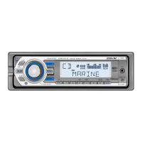
CDX-M60UI/MR60UI
4
SECTION 1
SERVICE NOTES
EXTENSION CABLE AND SERVICE POSITION
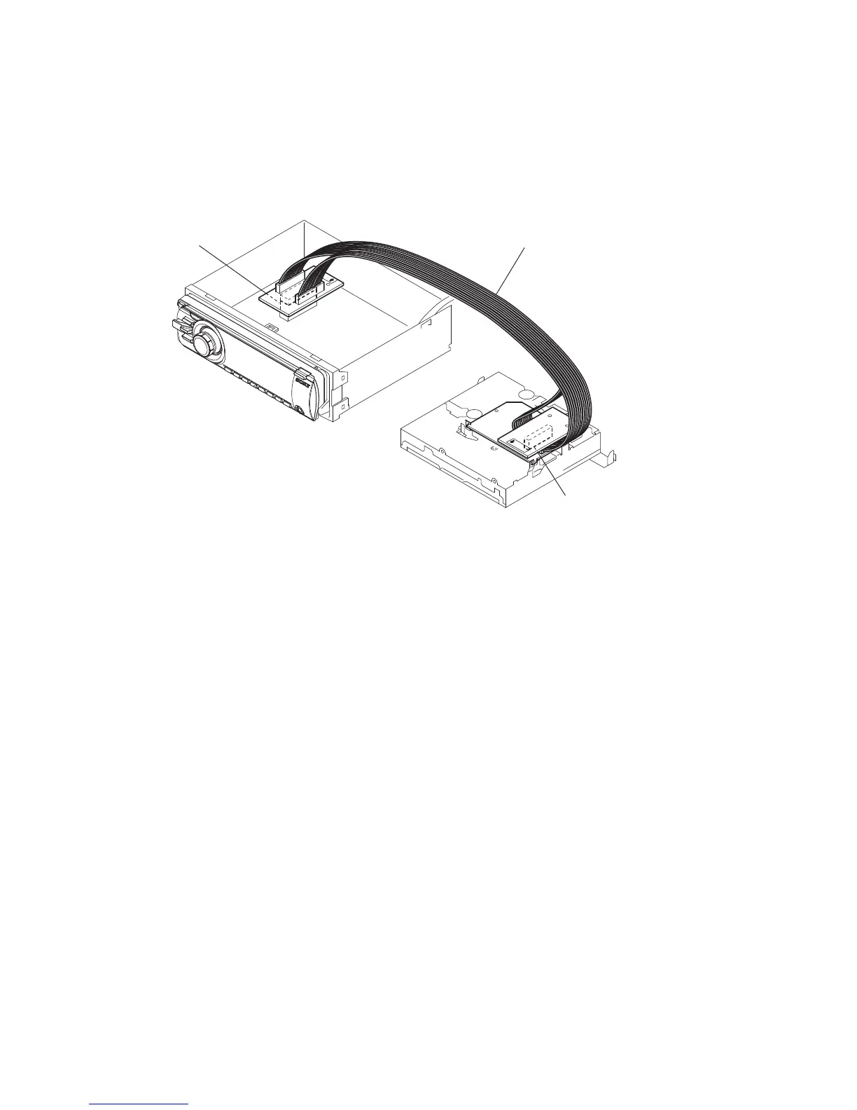
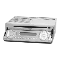
When repairing or servicing this set, connect the jig (extension
cable) as shown below.
• Connect the MAIN board (CN201) and the SERVO board
(CN401) with the extension cable (Part No. J-2502-076-1).
NOTE FOR REPLACEMENT OF THE SERVO BOARD
When repairing, the complete SERVO board (Part No. A-1554-
409-A) should be replaced since any parts in the SERVO board
cannot be repaired.
NOTE FOR THE 20-PIN CONNECTOR (CN901)
Do not use alcohol to clean the 20-pin connector (CN901) connect-
ing the front panel with the main body.
Do not touch the connector directly with your bare hand. Poor con-
tact may be caused.
SERVO BOARD
CN401
MAIN BOARD
CN201
J-2502-076-1



 To Next Page