Step
2
{Service
Mode operation}
l.
When
service mode is
set, the display will
change
6 times
(includes
âll
the segments lighting
and all
turning out), and
those 6 changes
will
be repeated
over and over.
When I key
is
pressed,
the
display
stops.
When I
key is released,
the
display
continues
to
change. This allows check of each
segment.
The
following operation
can
not
be
performed
if
the CD
holder is not
shut.
2. When
I
key is
pressed
on
each mode,
return
to
the
step l.
3.
When
})
or
li{
key is
pressed,
the optical
pick-
up block moves
to the inside or outside circum-
ference.
Tracking servo and sled servo
go
off when
this is done, so
press
REMAIN/ENTER key
to
turn
on the tracking servo
if
necessary.
4. When
)ll
key
is
pressed,
CLV-S
(pull-in
mode)
starts
while
performing
focus search. When
there
is
no disc installed,
focus
search
is repeated
several
times
while disc
motor is rotating.
5.
When
REMAINi ENTER key is
pressed,
tracking
servo, sled servo and CLV-A
(servo
during PLAY)
go
oN.
6.
When 4
and 5 are
performed,
the
disc
begins to
play.
Step 3
(Service
Mode release)
l. First be sure to unplug
the
power
cord then
remove
the TEST
point
solder
jumper.
(During
service mode,
C804
is discharged
by
un-
plugging
the
power
cord. Therefore, microcom-
puter
ICS0l is
reset
by
next
plugging
in the
power
cord.)
2. The set
will now operated normally.
NOTES ON
LASER DIODE
EMISSION
CHECK
The
laser
beam on this model
is concentrated
so as to
be focused on
the disc reflective
surface by
the
objective lens
in the optical
pick-up
block.
Therefore,
when checking
the laser diode
emission.
observe.
from more
than 30
cm away from
the objective
lens.
Laser Diode
Check
Procedu
re
The laser diode
on this
set
will
not emit
unless
the
CD
holder
is
closed and
S8l0
(leaf
SW type) is turned
on.
The laser diode will
always emit even
if focus
search is not
performed
in service mode.
Procedure:
Check the laser diode emission
with
the
eve.
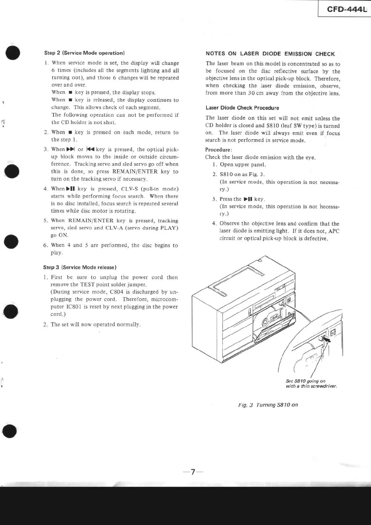
l. Open upper
panel.
2. S8l0 on
as
Fig.
3.
(In
service mode,
this operation
is not necessa-
rv.)
3.
Press
the
)ll
key.
(ln
service mode,
this operation
is
not
hecessa-
ry.)
4. Observe
the objective lens and
confirm
that the
laser diode
is
emitting
light.
If it
does
not,
APC
circuit
or optical
pick-up
block is defective.
Set S8l0
going
on
with a thin screwdriver.
Fig. 3 Turning
5810
on
o
-7