EasyManua.ls Logo

Sony CFD-444L - Page 25

Sony CFD-444L
56 pages
Print Icon
To Next Page IconTo Next Page
To Previous Page IconTo Previous Page
Loading...
I
"to-*ot
o
o
o
o
o
4
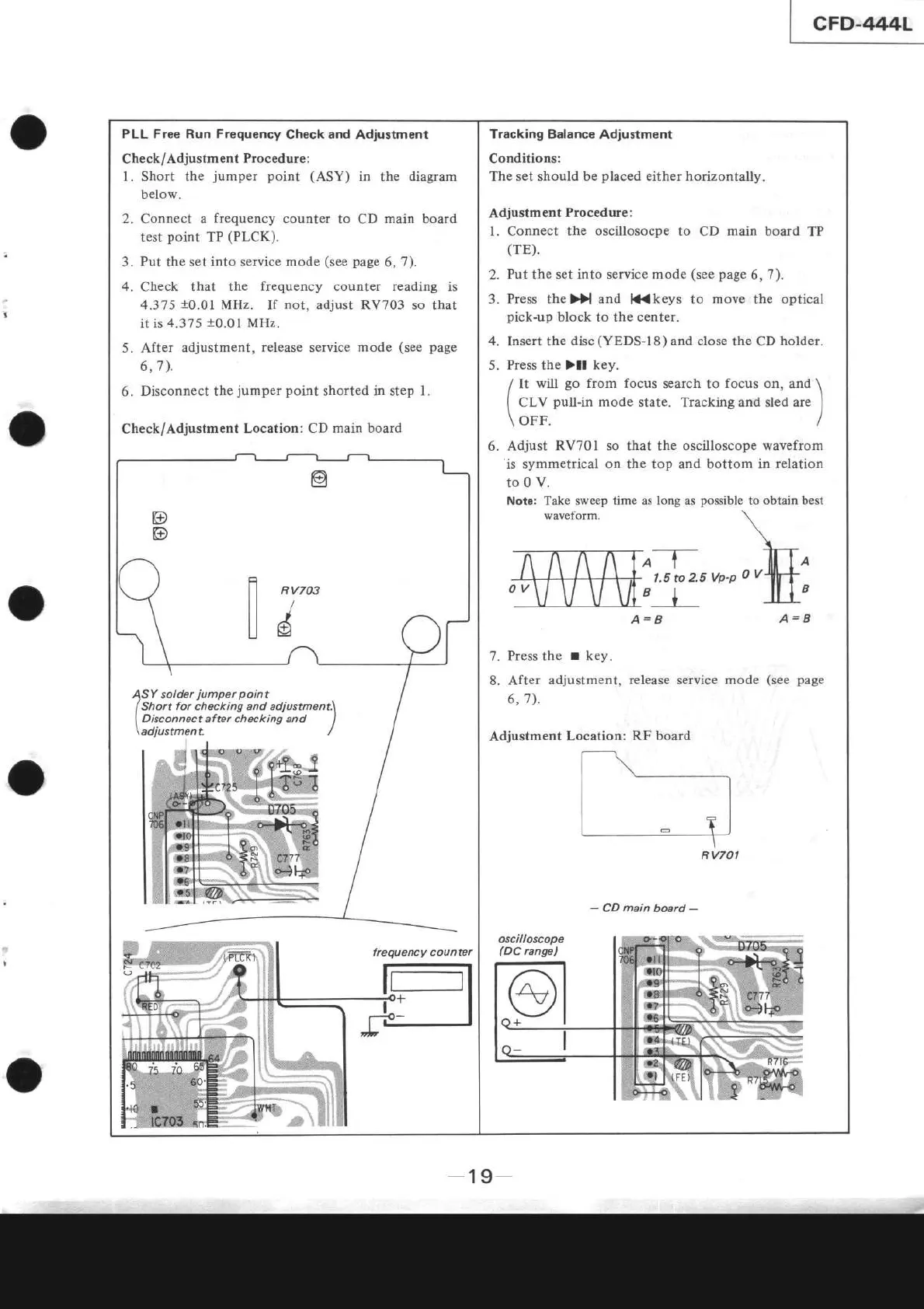
PLL Free Run Frequency
Check and Adiustment
Check/Adjustment
Procedure :
1. Short the
jumper
point (ASY)
in the diagram
below.
2. Connect a
frequency
counter
to CD
main board
test
point
TP
(PLCK).
Put
the set
into
service
mode
(see page
6,7).
Check that the
frequency
counter
reading
is
4.375
!0.01
MHz. If
not,
adjust RV703 so
that
it is
4.375
10.01
MHz.
5. After adjustment,
release service
mode
(see page
6,7).
6.
Disconnect the
jumper
point
shorted in step l.
Check/Adjustment
Locâtion:
CD main board
frequency counter
A= B
A=A
Press
the
r
key.
After
adjustment, release service mode
(see
page
6,7).
Adjustment
-
CD
main
board
-
Tracking Balance
Adiustment
Conditions:
The set should be
placed
either horizontally.
Adjustment
Procedure:
l.
Connect
the oscillosocpe to
CD
main board
TP
(TE).
2.
Put the set into service
mode
(see
page
6,7).
3.
Press the
Dl
and
ll{
keys to move the optical
pick-up
block
to the center.
Insert the
disc
(YEDS-I8)
and
close
the CD
holder.
Press the )ll key.
/
It will
go
from focus
search to
focus
on, and
\
I
CLV
pul-in
mode
state. Tracking and sled are
)
\
OFF.
/
6.
Adjust RV70l so that the oscilloscope wavefrom
'is
symmetricâl
on
the top and bottom in
relation
to0 V.
Note: Take sweep time as
long
as
waveform.
Dossible
to obtain best
A__T-
1.5
to
25 Vp-p
t_J_
Locâtion:
RF board
t.--=--_
ll
tl
| _ +l
\-_=---]-
RV701
5.
7.
8.
SY solder
iumper
point
Short
for checking
and adiustment\
Disconnect after chæking and
I
adjustment /
-19-