MICROFILM
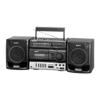
CFS-K1066/K1066S
SERVICE MANUAL
RADIO CASSETTE-CORDER
SPECIFICATIONS
E Model
Model Name Using Similar Machanism NEW
Tape Transport Mechanism Type MF-K1066
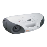
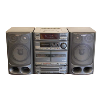
Photo : CFS-K1066S
Frequency range CFS-K1066
FM : 87.6 – 108MHz
AM : 530 – 1,710kHz
CFS-K1066S
FM : 87.6 – 108MHz
MW : 530 – 1,605kHz /SW1 : 2.3 – 7 MHz/
SW2 : 7 – 22MHz
IF FM : 10.7MHz/AM/MW/SW : 455kHz
Aerials FM/SW : Telescope/AM/MW : Built-in ferrite bar
Recording system 4-track, 2-channel stereo
Frequency response 100 – 10,000Hz
Speakers Woofer : 10cm (4 inches) dia., cone type/
Tweeter : 2cm (
4
/
5
inches) dia.
Input Mixing microphone input jack (mini jack) (2),
sensitivity 3 mV. for low impedance microphone
Output Headphones jack (stereo minijack),
for 16 – 68 ohms impedance headphones
Maximum Power output
2.3W+2.3W
Battery life FM Recording : Sony R20P : Approx. 16 hours/
Sony LR20 alkaline : Approx. 36 hours
Playback : Sony R20P : Approx. 8 hours/Sony
LR20 alkaline : Approx. 21 hours
Power requirements CFS-K1066 : 220V AC 60Hz
CFS-K1066S : 110 – 120V/220 – 240V AC
selectable, 50/60Hz
Power consumption AC 14 W
Dimensions Approx. 579 x 206 x 197 mm (w/h/d)
(22
7
/
8
x 8
1
/
8
x 7
7
/
8
inches) incl. projecting and
controls, not incl. handle
Mass Approx. 4.6 kg (10 lb 2 oz) incl. batteries
Supplied Accessories
AC power cord (1),
Microphone (1)
Design and specifications are subject to change without notice.