EasyManua.ls Logo

Sony CFD-S22 Service Manual

Sony CFD-S22
68 pages
To Next Page IconTo Next Page
Page #1 background imageLoading...
Page #1 background image
– 1 –
Sony Corporation
Personal Audio Group
Published by Sony Engineering Corporation
CD
Model Name Using Similar Mechanism CFD-S38
Section
CD Mechanism Type KSM-213CDM
Optical Pick-up Name KSS-213C
TC
Model Name Using Similar Mechanism CFD-S38
Section
Tape Transport Mechanism Type MF-S22-117
SERVICE MANUAL
US Model
Canadian Model
E Model
Australian Model
CFD-S22/S32
Tourist Model
CFD-S22
CFD-S22/S32
CD RADIO CASSETTE-CORDER
Other Specifications
CD player section
System
Compact disc digital audio system
Laser diode properties
Material: GaAlAs
Wave length: 780 nm
Emission duration: Continuous
Laser output: Less than 44.6 µW
(This output is the value measured at a distance of
about 200 mm from the objective lens surface on
the optical pick-up block with 7 mm aperture.)
Spindle speed
200 r/min (rpm) to 500 r/min (rpm) (CLV)
Number of channels
2
Frequency response
20 - 20,000 Hz +1/–2 dB
Wow and flutter
Below measurable limit
SPECIFICATIONS
– Continued on next page –
Radio section
Frequency range
US, CND, E92, MX model:
FM: 87.6 - 108 MHz
AM: 530 - 1,710 kHz
SP, AR, AUS, E4, JE model:
FM: 87.5 - 108 MHz or 87.6 - 108 MHz
AM: 531 - 1,602 kHz
Antennas
FM: Telescopic antennas
AM: Built-in ferrite bar antennas
Cassette-corder section
Recording system
4-track 2 channel stereo
Fast winding time
Approx. 120 sec. with Sony cassette C-60
Frequency response
TYPE I (normal): 70 - 10,000 Hz
General
Speaker
Full range: 10 cm (4 in.) dia.,
3.2 ohms, cone type (2)
Outputs
Headphones jack (stereo minijack)
For 16 - 68 ohms impedance headphones
AUDIO POWER SPECIFICATIONS (US Model)
POWER OUTPUT AND TOTAL
HARMONIC DISTORTION
With 3.2-ohm loads, both channels driven from
150 - 6,300 Hz; rated 1.8 W per channel-
minimum RMS power, with no more than 10%
total harmonic distortion in AC operation.
Photo: CFD-S32 (Silver)
9-927-674-15
2005I04-1
© 2005.09
Ver. 1.5 2005.09
Question and Answer IconNeed help?

Do you have a question about the Sony CFD-S22 and is the answer not in the manual?

Sony CFD-S22 Specifications

General IconGeneral
TypePortable Stereo System
CD PlayerYes
Radio TunerAM/FM
Cassette PlayerYes
Media TypeCD, Cassette, Radio
Power SourceAC or Batteries

Summary

SPECIFICATIONS

AUDIO AND PERFORMANCE SPECIFICATIONS

Details audio output, radio, CD, cassette specs.

GENERAL SPECIFICATIONS

Covers speaker details and output jack information.

CAUTIONS AND NOTES

GENERAL CAUTIONS AND HANDLING GUIDELINES

Covers radiation, circuit board, chip, and pick-up handling.

LASER DIODE EMISSION CHECK

Procedure and safety for checking laser diode emission.

SAFETY-RELATED COMPONENT WARNING

Identifies critical safety components for replacement.

SERVICING NOTES

CHUCK PLATE JIG USAGE

Describes the use of a specific jig for CD section repair.

LASER DIODE FOCUS SEARCH CHECK

Procedure to check laser diode and focus search operation.

GENERAL OPERATION

LOCATION OF CONTROLS

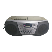
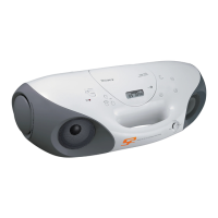
Identifies buttons and features on the unit and remote.

SOUND EMPHASIS ADJUSTMENT

Explains how to adjust MEGA BASS and TONE for sound emphasis.

DISASSEMBLY

CABINET (FRONT) SUB ASSY REMOVAL

Details steps for removing the front cabinet assembly.

WIRE HARNESS ROUTING AND CONNECTION

Guides on routing and connecting wires between cabinets.

BOARD REPLACEMENT PROCEDURES

Instructions for accessing secondary, power, VOL SEL, and tuner boards.

MECHANISM AND CABINET DISASSEMBLY

Steps for upper cabinet, main board, CD, tape mechanisms, and cassette holder.

PRE BOARD REPLACEMENT

Instructions for accessing and replacing the PRE board.

MECHANICAL ADJUSTMENTS

TORQUE MEASUREMENT

Procedures for measuring tape mechanism torque.

TAPE TENSION MEASUREMENT

Procedures for measuring tape tension.

ELECTRICAL ADJUSTMENTS

TAPE SECTION ADJUSTMENTS

Details output level and tape speed adjustment for the tape section.

TUNER SECTION ADJUSTMENTS

FM/AM SECTION SPECIFICATIONS AND ADJUSTMENTS

Covers FM/AM frequency coverage and tracking procedures.

CD SECTION ADJUSTMENTS

FOCUS BIAS CHECK

Procedure to check and confirm focus bias using an oscilloscope.

DIAGRAMS

IC PIN DESCRIPTION

Details pin functions for IC501 (System Control).

CIRCUIT BOARDS LOCATION

Identifies the physical location of various circuit boards.

BLOCK DIAGRAM - CD SECTION

BLOCK DIAGRAM - MAIN SECTION

PRINTED WIRING BOARD - TUNER SECTION

SCHEMATIC DIAGRAM - TUNER SECTION

PRINTED WIRING BOARD - CD SECTION

SCHEMATIC DIAGRAM - CD SECTION

SCHEMATIC DIAGRAM - PRE SECTION

PRINTED WIRING BOARDS - MAIN SECTION

SCHEMATIC DIAGRAM - MAIN SECTION (1/2)

SCHEMATIC DIAGRAM - MAIN SECTION (2/2)

PRINTED WIRING BOARD - CONTROL SECTION

SCHEMATIC DIAGRAM - CONTROL SECTION

PRINTED WIRING BOARDS - POWER SUPPLY SECTION

SCHEMATIC DIAGRAM - POWER SUPPLY SECTION

IC BLOCK DIAGRAMS

EXPLODED VIEWS

CABINET (FRONT) SECTION

Exploded view of the front cabinet parts.

CABINET (REAR) SECTION

Exploded view of the rear cabinet parts.

CABINET (UPPER) SECTION

Exploded view of the upper cabinet parts.

TAPE MECHANISM SECTION-1

TAPE MECHANISM SECTION-2

OPTICAL PICK-UP SECTION

ELECTRICAL PARTS LIST

SUPPLEMENT-1

CHANGE OF CD BOARD

Details changes related to the CD board.

CHANGE OF MAIN BOARD

Details changes related to the Main board.

ELECTRICAL ADJUSTMENT

FOCUS BIAS CHECK

Procedure to check and confirm focus bias using an oscilloscope.

IC PIN DESCRIPTION

IC501 CXP83620-025Q/026Q (SYSTEM CONTROL)

Pin functions for the system control IC.

Related product manuals