– 16 –
TP
(RF)
TP
(RF)
– CD board (conductor side) –
TP(VT)
TP
(VT)
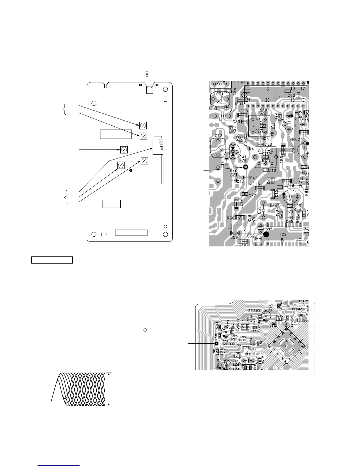
– tuner board (conductor side) –
Adjustment Location:
CD SECTION
CD section adjustments are done automatically in this set.
In case of operation check, confirm that focus bias.
FOCUS BIAS CHECK
1. Connect the oscilloscope between IC701 pin qg (or TP (RF))
and GND on CD board.
2. Insert the disc (YEDS-18). (Part No. : 3-702-101-01)
3. Press the CD N X button.
4. Confirm that the oscilloscope waveform is as shown in the
figure below. (eye pattern)
A good eye pattern means that the diamond shape ( ) in the
center of the waveform can be clearly distinguished.
• RF signal reference waveform (eye pattern)
Test Point:
RF level :
1.2 ± 0.3 Vp-p
VOLT/DIV : 50 mV (10 : 1 probe in use)
TIME/DIV : 500 nS
When observing the eye pattern, set the oscilloscope for AC range
and raise vertical sensitivity.
TP
(VT)
IC1
IC2
CNP1
JW2
ANT1
FM
TELESCOPIC
ANTENNA
L3
L4
AM
TRACKING
ADJUSTMENT
CT3
L1
CT1
FM
TRACKING
ADJUSTMENT
L2
FM
FREQUENCY
COVERAGE
ADJUSTMENT
– tuner board (component side) –