EasyManua.ls Logo

Sony HCD-H51 Service Manual

Sony HCD-H51
54 pages
To Next Page IconTo Next Page
Page #1 background imageLoading...
Page #1 background image
HCD-H51/H51M
SERVICE
MANUAL
HCD-H51
and
HCD-H51M
are
the
tuner,
deck,
CD
and
amplifier
section
in
FH-B510
and
MHC-510
respectively.
HCD-HS51M
destined
for
UK
does
not
include
speaker
system
that
is
supplied
separately.
Photo
:
HCD-H51
US
Model
Canadian
Model
UK
Model
HCD-H51M
AEP
Model
HCD~-
H51/H51M
SPECIFICATIONS
AUDIO
POWER
SPECIFICATIONS
(For
the
customers
in
the
USA
Model)
POWER
OUTPUT
AND
TOTAL
HARMONIC
DISTORTION
:
With
6
ohm
loads,
both
channels
driven,
from
60
Hz-
20
kHz;
rated
20
watts
per
channel
minimum
RMS
power,
with
no
more
than
1%
total
harmonic
distortion
from
250
miliwatts
to
reted
output.
Tuner
section
FM
stereo,
FM/AM
superheterodyne
tuner
FM
tuner
section
Tuning
range
East
European
model:
65.0-74.0
MHz
87.5-
1080
MHz
Other
country
model:
87.5-108.0
MHz
Antenna
FM
lead
antenna
(for
HCD-H51M)
Telescopic
antenna
(for
HCD-H51).
Antenna
terminals
75
ohm
unbalanced
intermediate
frequency
10.7
MHz
AM
tuner
section
Tuning
range
US
and
Canadian
model
AM
:
§30-1,710
kHz
Italian
model
AM
:
622
~
1,611
kHz
MICROFILM
Model
Name
Using
Similer
Mechanism
|
HCD-H170/H170K/H700
cD
Section
CD
Mechanism
Name
CDM13B-58D4E
Base
Unit
Name
BU-5BD4E
|
Deck
Model
Name
Using
Similar
Mechanism]
HST-H1750
Section
|
Tape
Transport
Mechanism
Type
TCM-210W2
UK,
East
European,
AEP,
Germany,
AED
and
CIS
model
MW
:
531-1,602
kHz
LW
:
153-279
kHz
Antenna
AM
loop
antenna
External
antenna
terminals
Intermediate
frequency
450
kHz
Amplifier
section
For
UK,
East
European,
AEP,
Germany,
Italian,
AED
and
CIS
model:
Continuous
RMS
power
output
:
25+
25
watts
(6
ohms
at
1
kHz,
DIN)
30
+30
watts
(6
ohms
at
1
kHz,
5%
THD)
Music
power
output
:
75+
75
watts
(6
ohms
at
1
kHz,
10%
THD)
For
US
and
Canadian
model
:
Continuous
RMS
power
output
:
30
+30
watts
(6
ohms
at
1
kHz,
5%
THD)
For
Australian
model
:
Continuous
RMS
power
output
:
30
+30
watts
6
ohms
at
1
kHz,
5%
THD)
Peak
music
power
output
:
300
watts
Inputs
For
HCD-H51
=PHONO
(phono
jack)
:
sensitivity
5
mV,
impedance
47
kirohms
For
HCD-H51M
UK,
AEP
and
AED
model:
PHONO
(phono
jack)
:
sensitivity
5
mV,
impedance
47
kilohms
Outputs
HEADPHONES
(stereo
minijack)
:
accept
headphones
of
8
ohms
or
more.
:
SPEAKERS
:
accept
impedence
of
6
to
16
ohms.
Cassette
deck
section
Recording.
system
4-track
2-channel
stereo’
Frequency
response
(DOLBY
NR
OFF)
60-
13,000
Hz
(+3
db),
using
TYPE
|
cassette
(Sony
HF-S)
60-14,000
Hz
(+3
dB),
using
TYPE
II
cassette
(Sony
UX-S
)
Wow
and
flutter
0.1%
WRMS
+0.3%
(DIN)
Compact
disk
player
section
System
Compact
disk
digital
audio
system
Laser
‘Semiconductor
laser
Wavelength
780
-
790
nm
Note
:
AED
:
Denmark
model
—Continued
on
next
page—
COMPACT
DISK
DECK
RECEIVER
SONY.
Question and Answer IconNeed help?

Do you have a question about the Sony HCD-H51 and is the answer not in the manual?

Sony HCD-H51 Specifications

General IconGeneral
BrandSony
ModelHCD-H51
CategoryPortable Stereo System
LanguageEnglish

Summary

Specifications

Audio Power Specifications

Power output and total harmonic distortion details.

Tuner Section Specifications

FM/AM tuning range, intermediate frequency, and antenna details.

Amplifier Section Specifications

Continuous RMS power output and music power for different regions.

General Information and Safety

Safety Labels and Warnings

Describes caution labels and critical component warnings.

Servicing Notes and Setup

Model Identification Details

Details on specification labels and model numbers.

Parts Identification

Front Panel and Tuner Section Parts

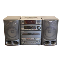
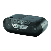
Identification of parts on the front panel and tuner section.

Amplifier and Cassette Deck Section Parts

Identification of parts in the amplifier and cassette deck sections.

Disassembly Procedures

Case Assembly Disassembly

Steps for disassembling the main case.

Power Board Removal

Procedure for removing the power board.

Main Board Removal

Procedure for removing the main board.

CD Mechanism Block Removal

Procedure for removing the CD mechanism.

Deck Mechanism Block Removal

Procedure for removing the deck mechanism.

Mechanical Adjustments

Electrical Adjustments

Deck Section Servicing Notes

Notes, switch positions, and test tapes for deck adjustments.

Deck Torque and Level Adjustments

Procedures for adjusting deck torque and playback levels.

Tape Speed Adjustment Procedures

Steps for adjusting tape speed for Deck A.

Playback Level Adjustment Procedures

Steps for adjusting playback levels for Decks A and B.

Record Bias Adjustment (Deck B)

Procedure for adjusting record bias on Deck B.

FM Section Adjustments

Settings and calibration for the FM tuner section.

Diagrams and Schematics

Exploded Views

Electrical Parts List

BD Board Parts List

Comprehensive list of electrical components for the BD board.

Related product manuals