Do you have a question about the Sony CMT-G1BIP and is the answer not in the manual?
Technical details on power, dimensions, mass, and included accessories.
List of supplied accessories with part numbers and descriptions.
Precautions for handling optical pick-up, laser diode, solder, and component replacement.
Notes on disassembly, assembly, operation checks, grounding, model ID, and tray lock.
Disassembly flowchart and steps for removing the case, front panel, and rear panel assemblies.
Procedures for removing the main board, AMP board, power transformer, and CD mechanism.
Instructions for removing the base unit, optical pick-up, DCDC board, CD holder, and belt.
Procedures for Cold Reset, Auto Standby, and CD Ship Mode.
Modes for testing functions like Auto Standby, Amplifier, Panel keys, and CD sled motor.
Procedure to check FM tuner sensitivity and signal reception using a signal generator.
Signal path diagrams for various sections including CD, USB, Tuner, and Amplifier.
Location, PWB layouts, and schematic diagrams for key circuit boards.
Exploded views of the overall unit, front panel, and rear panel assemblies.
Exploded views for the main board, chassis, CD mechanism deck, and associated parts.
List of capacitors, transformers, and coils with part numbers and specifications.
List of transistors, resistors, ICs, connectors, diodes, and filters with part numbers.
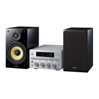
| Bass reflex | - |
|---|---|
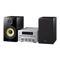
| Speaker type | 2-way |
| RMS rated power | 60 W |
| Number of speakers | 2 |
| Cassette deck | No |
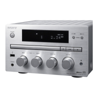
| Product color | Black, Silver |
| Supported radio bands | AM, DAB, FM |
| Radio Data System (RDS) | Yes |
| Display type | LCD |
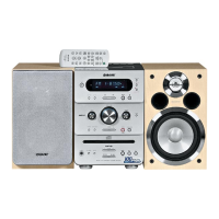
| Apple docking compatibility | iPhone, iPod |
| USB 2.0 ports quantity | 1 |
| Power source | AC |