– 10 –
Focus/Tracking Gain Adjustment
A servo analayzer is necessary in order to perform this adjustment
exactly.
However, this gain has a margin, so even if it is slightly off,
there is no problem. Therefore, do not perform this adjustment.
Focus/tracking gain determines the pick-up follow-up relative to
mechanical noise and mechanical shock when the 2-axis device
operates. However, as these reciprocate, the adjustment is at the
point where both are satisfied.
• When gain is rased, the noise when 2-axis device operates in-
crease.
• When gain is lowered, it is more susceptible to mechanical shock
and skipping occurs more easily.
This adjustment has to be performed upon replacing any of the
following parts.
• Optical pick-up
• RV503 (Focus gain VR)
• RV502 (Tracking gain VR)
Normally, be sure not to move RV503 (focus gain VR) and
RV502 (tracking gain VR).
Adjustment method:
– Focus Gain Adjustment –
This adjustment is not performed.
If focus gain VR RV503 is turned, set to mechanical center.
– Tracking Gain Adjustment –
(perform at normal operation)
1. Place the optical pick-up level, horizontally. (If the optical
pick-up is not level, the 2-axis device will be weighted and
adjustment cannot be done.)
2. Connect the oscilloscope to TP (TE) and TP520 (VC) on MAIN
board.
3. Set the disc (YEDS-18) and press the ^ key.
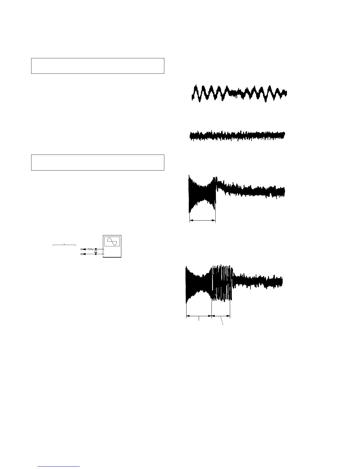
4. Turn RV502 slightly clockwise (tracking gain drops) and ob-
tain a waveform with a fundamental wave (waveform has large
waves) as in Figure 1.
5. Turn RV502 slowly counterclockwise (tracking gain rises) until
the fundamental wave disappears (no large waves) as in Fig-
ure 2.
6. Set RV502 to the position about 30˚ counterclockwise form
the position obtained in step 5. If RV502 contact point is more
than 90˚ counterclockwise from mechanical center, tracking
gain is too high. In this case, readjust from step 4.
7. Press + or = key and observe the 100 track jump wave-
form. Check that no traverse waveform appears for both +
or = directions. (See Figures 3 and 4.) It is acceptable if
the traverse waveform appears only now and then, but if it
appears constantly, raise tracking gain slightly and check step
7 again.
8. Check that there is not abnormal amount of operation noise
(white noise) from the 2-axis device. If there is, tracking gain
is too high, readjust starting with step 4.
The waveforms are those measured with the oscilloscope set as
shown below.
• VOLT/DIV: 500 mV
• TIME/DIV: 5 ms
• Waveform when tracking gain is lowered.
Fundamental wave appears (large waves).
Fig. 1
• Waveform when fundamental wave disappears (no large waves).
Fig. 2
• Waveform with no traverse waveform during 100 track jump.
(Brake application is smooth because of adjustment.)
Fig. 3
• Waveform with traverse waveform during 100 track jump.
(Brake application is poor because of adjustment.)
Fig. 4
100 track