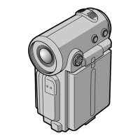
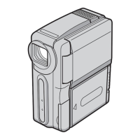
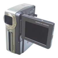
Do you have a question about the Sony DCR-IP1 and is the answer not in the manual?
Essential repair guidelines for cable connections and power supply during servicing.
Step-by-step guide to manually eject a cassette when the unit fails to eject normally.
Overview of error reporting via self-diagnosis display and code tables for troubleshooting.
Steps for removing top cabinet, F panel, and Cabinet R block assemblies.
Procedure for accessing and removing the PD-199 board and LCD module.
Instructions for removing the mechanism deck, IF-108, VC-333 boards, and associated parts.
Diagrams showing the location of circuit and flexible boards within the unit.
First part of the overall block diagram, detailing signal paths and component interconnections.
Second segment of the overall block diagram, illustrating further system interconnections and signal flows.
Initial section of the power block diagram, detailing power supply distribution and regulation.
Schematic diagrams illustrating the frame and main board interconnections.
Detailed schematics for important boards like FP-723, PD-199, IF-108, MS-153, SE-139.
Printed wiring board layouts for PD-199, IF-108, MS-153, and SE-139 boards.
Exploded views of overall, panel, cabinet, lens, mic, and mechanism assemblies.
Exploded views of W100 mechanism deck, LS chassis, and mechanism chassis assemblies.
Comprehensive list of electrical components with part numbers and descriptions.
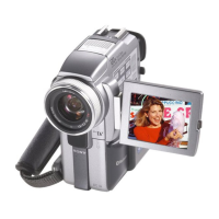
| Optical Zoom | 10x |
|---|---|
| Digital Zoom | 120x |
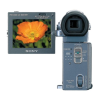
| Screen Size | 2.5 inches |
| Type | Digital Camcorder |
| Recording Media | MiniDV |
| Lens | Carl Zeiss |
| Image Sensor | 1/4.7-inch CCD |