6-15
10. IRIS IN/OUT Adjustment
For the unit to judge if the white balance is indoors or outdoors in
auto white balance operations, measure the light level and write it in
the EEPROM.
If the level is not correct, the white balance will not be accurate.
Switch setting:
1) STEADY SHOT switch (Menu display) OFF
Adjusting method:
1) Set data: 01 to page: 1, address: 00.
2) Set data: 41 to page: D, address: 10, and press the PAUSE button
of the adjusting remote commander.
3) Set data: 01 to page: 6, address: 00.
4) Set data: 06 to page: 6, address: 04.
5) Set data: 02 to page: 6, address: 40.
6) Set data: 0B to page: 6, address: 01, and press the PAUSE button
of the adjusting remote commander.
7) Read the DDS display data (Note 1), and take the upper two digits
as D
1 and the lower two as D2.
8) Convert D
1 to a decimal number and obtain D1'. (Refer to Table
6-4-2. “Hexadecimal Notation-Decimal Notation Conversion
Table” of “Service mode”.)
9) Calculate D
3' using the following equations. (Equations 1 and 2
are for decimal notation calculation)
When D
2 ≥ D0
D
3' = D1' – 21 ...................................... Equation 1
When D
2 < D0
D
3' = D1' – 22 ...................................... Equation 2
10) Convert D
3' to a hexadecimal number and obtain D3.
11) Set D
3 to page: F, address: 36, and press the PAUSE button of
the adjusting remote commander.
12) Set data: 09 to page: 6, address: 01, and press the PAUSE button
of the adjusting remote commander.
13) Read the DDS display data (Note 1), and take the upper two
digits as D4 and the lower two as D5.
14) Convert D
4 to a decimal number and obtain D4'. (Refer to Table
6-4-2. “Hexadecimal Notation-Decimal Notation Conversion
Table” of “Service mode”.)
15) Calculate D
6' using the following equations. (Equations 3 and 4
are for decimal notation calculation)
When D
5 ≥ F0
D
6' = D4' – 13 ...................................... Equation 3
When D
5 < F0
D
6' = D4' – 14 ...................................... Equation 4
>
>
>
>
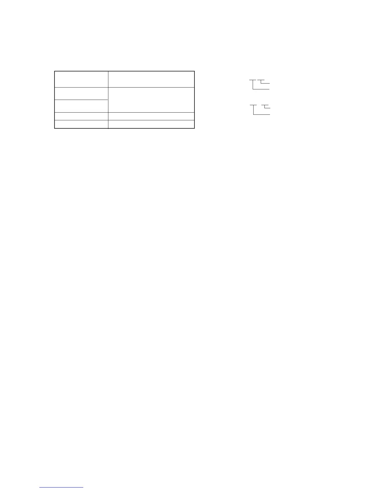
Subject
Clear chart
(Color bar standard picture frame)
F
36, 37
Measurement Point
Measuring Instrument
Adjustment Page
Adjustment Address
DDS display of EVF or LCD, or page:
A display data of the adjusting remote
commander
16) Convert D6' to a hexadecimal number and obtain D6.
17) Set D
6 to page: F, address: 37, and press the PAUSE button of
the adjusting remote commander.
Note 1: The right four digits of the display data at the right bottom
side of the EVF and LCD is the LIGHT LEVEL data.
00 XXXX
Lower two digits
Upper two digits
Note 2: A page display data
A : XX : XX
Lower two digits
Upper two digits
Processing after Completing Adjustments
1) Set data: 00 to page: D, address: 10, and press the PAUSE button
of the adjusting remote commander.
2) Set data: 00 to page: 1, address: 00.
3) Set data: 00 to page: 6, address: 01, and press the PAUSE button
of the adjusting remote commander.
4) Set data: 00 to page: 6, address: 40.
5) Set data: 00 to page: 6, address: 04.
6) Set data: 00 to page: 6, address: 00.


 To Next Page
 Loading...