6-14
9. Color Reproduction Adjustment
Adjust the color separation matrix coefficient so that the proper color
reproduction is produced.
Note: NTSC model : DCR-PC7
PAL model : DCR-PC7E
Adjusting method:
1) Set data: 01 to page: 6, address: 00.
2) Set data: 3D to page: 6, address: 01, and press the PAUSE button
of the adjusting remote commander.
3) Set data: 3F to page: F, address: 16, and press the PAUSE button
of the adjusting remote commander.
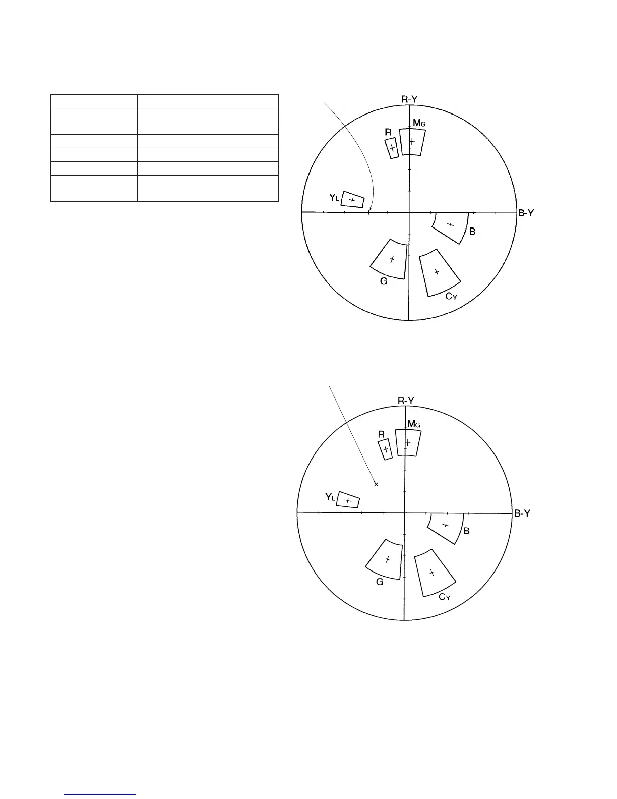
4) Adjust the GAIN and PHASE of the vectorscope, and adjust the
burst luminance point to the burst position of the color
reproduction frame.
5) Change the data of addresses 2E, 30, 8F and 90 of page: F, and
settle each color luminance point in each color reproduction frame.
Note 1: Be sure to press the PAUSE button of the adjusting
remote commander before changing the addresses.
If not, the new data will not be written to the memory.
6) Press the PAUSE button of the adjusting remote commander.
Processing after Completing Adjustments
1) Set data: 00 to page: 6, address: 01 and press the PAUSE button
of the adjusting remote commander.
2) Set data: 00 to page: 6, address: 00.
For NTSC model
Fig. 6-1-9.
For PAL model
Fig. 6-1-10.
Burst position
Burst position
Subject
Color bar chart standard picture frame
Measurement Point
Measuring Instrument
Adjustment Page
Adjustment Address
Specified Value
Video output terminal of VIDEO/
AUDIO output jack.
Vectorscope
F
2E, 30, 8F, 90
All color luminance points should settle
within each color reproduction frame.


 To Next Page