3
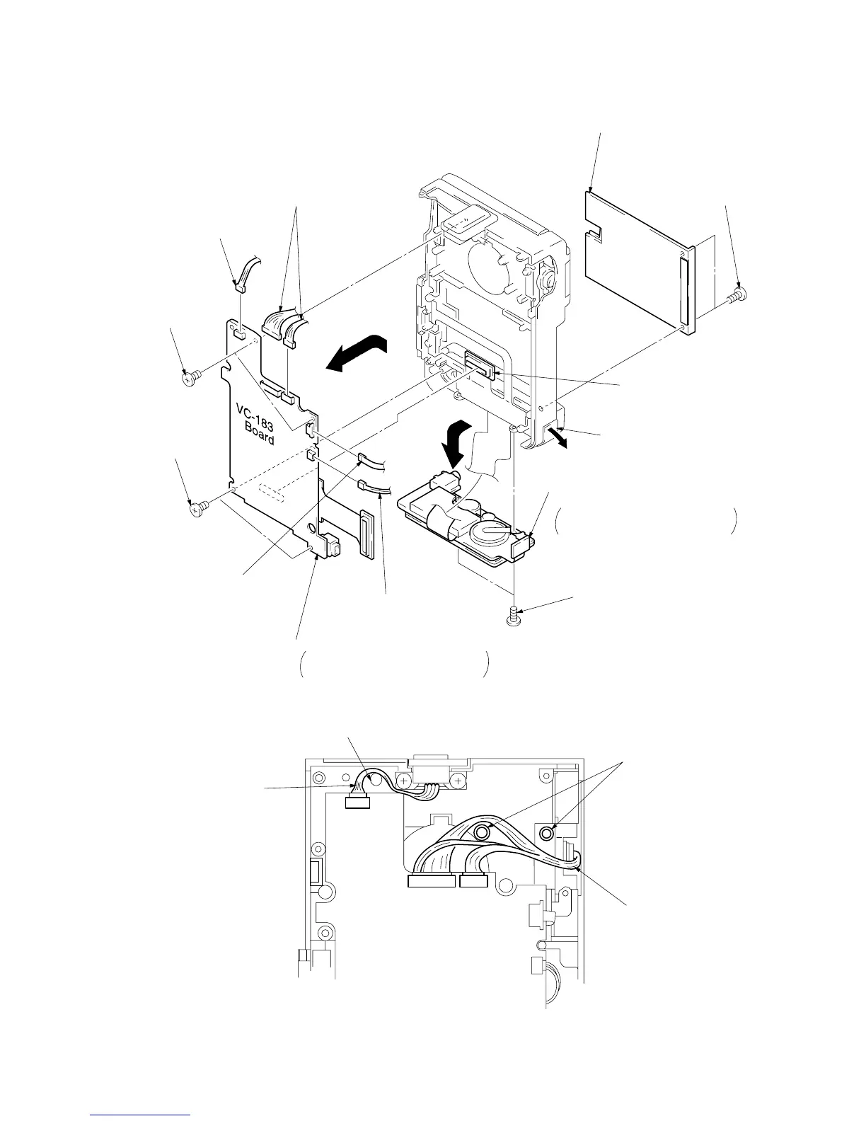
Board-to-board connector 60P
CN6200, VC-183 board
CN3700, DD-91 board
8
Two screws (M1.7 x 2.5)
1
Two screws (M1.7 x 2.5)
2
Battery plate
!™
Two screws
(M1.7 x 2.5)
!¡
Two screws
(M1.7 x 2.5)
7
Connector
CN4701, 2P
4
Connector
CN4700, 4P
5
Two connectors
CN1001, 6P
CN1002, 11P
6
ME4800 control switch block
CN2301, 5P
!º
Remove the DV terminal cover
in the arrow
B
direction.
9
Remove the cabinet bottom assembly
in the arrow
A
direction.
Be careful not to damege the flexible
board of the DD-91 board.
B
A
C
!£
Remove the VC-183 board in the arrow
C
direction.
When assembling, pay attention to the
positioning of the harness. See Fig. 1.