2-4
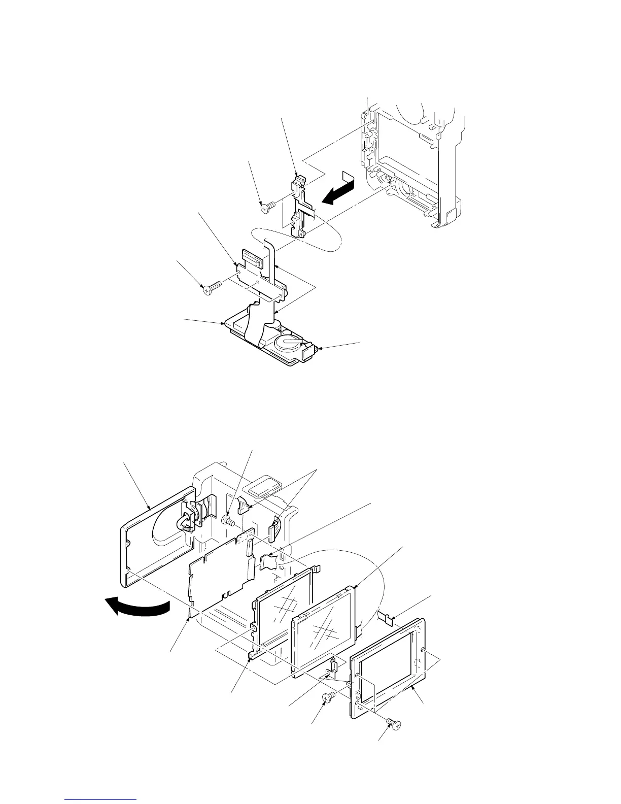
2-6. REMOVAL OF DD-91 BOARD
Note : Be careful not to damage the flexible board.
Cabinet bottom assembly
DD-91 board
(Video terminal)
1
Three screws (M2 x 6)
3
Two screws (M1.7 x 2.5)
4
Remove the battery terminal board
in the arrow direction.
2
DD-91 board
(S terminal, 26-pin multi connector)
!º
Screw (M1.7 x 2.5)
1
Open the liquid crystal panel
in the arrow directioen.
2
Three screws (M1.7 x 4)
3
LCD case (Inner)
5
PD ground plate
4
Screw (M1.7 x 2.5)
!¡
PD-71 board
!™
Cold cathode fluorescent tube with
conductive light plate.
9
Liquid crystal display module
(LQ3FN31)
6
FP-484 flexible boar