2-5
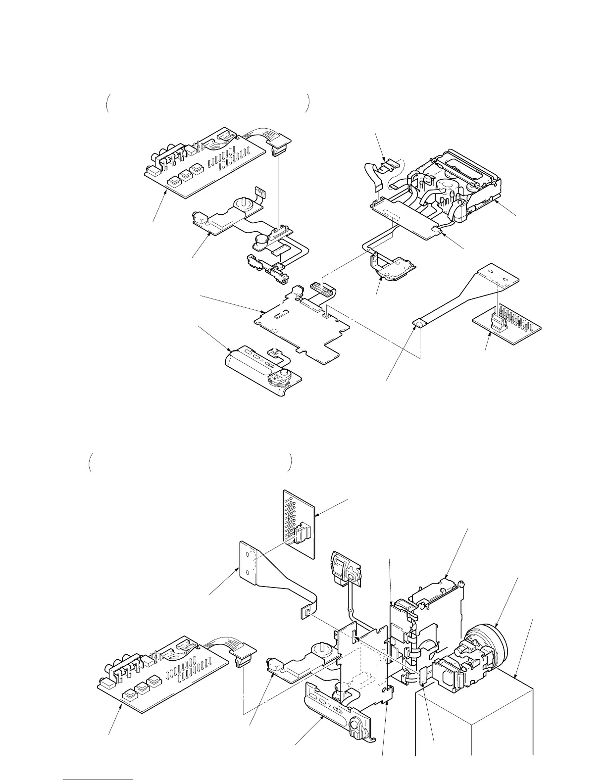
2-8. SERVICE POSITION-1 (MAINLY VIDEO/AUDIO SYSTEM CHECKS AND ADJUSTMENTS)
CPC-6 terminal board
(J-6082-371-A)
CPC-6 : 26P multi connector
Flexible board (CPC-6) for pulling out CPC terminal
(J-6082-370-A)
VC-183 : CN6202
I/O board 1
(J-6082-372-A)
DD-91 : 26P multi connector
1
Remove each board according to “DISASSEMBLY”.
2
Connect the specified tool as shown in the figure.
Take note that connectors can be connected in the opposite
direction depending on their shapes.
MR-36 board
Mechanism deck
Zoom lens
Box or table.
CD-159 board
VC-183 board
DD-91 board
VK4800 control switch block
2-9. SERVICE POSITION-2 (MAINLY CAMERA SYSTEM CHECKS OR ADJUSTMENTS)
1
Remove each board according to “DISASSEMBLY”.
2
Connect the specified tool as shown in the figure.
Take note that connectors can be connected in the opposite
direction depending on their shapes.
DD-91 board
VC-183 board
VK4800 control switch block
FZ4800 control switch block
MR-36 board
Mechanism deck
I/O board 1
(J-6082-372-A)
DD-91 : 26P multi connector
Flexible board (CPC-6) for pulling out CPC terminal
(J-6082-370-A)
VC-183 : CN6202
CPC-6 terminal board
(J-6082-371-A)
CPC-6 : 26P multi connecto