6-21
3. Bright Adjustment (VF-106 board)
Set the level of the VIDEO signal for driving the LCD to the specified
value. If deviated, the screen image will be blackish or saturated
(whitish).
Note 1: Confirm that the specified value of “Input Level
Adjustment” of “LCD SYSTEM ADJUSTMENT” is
satisfied , and perform this adjustment.
Connection:
In case connect the oscilloscope to Pin !ª of CN6202 (EVF VG),
connect Pin !ª of CN6202 and Pin !¡ (GND) with a 680 Ω resistor.
680 Ω resistor: 1-249-415-11
Adjusting method:
1) Set data: 01 to page: 1, address: 00.
2) Input the following data to page: D, addresses: E8 to ED.
4. Contrast Adjustment (VF-106 board)
Set the level of the VIDEO signal for driving the LCD to the specified
value. If deviated, the screen image will not be consistent or will be
blackish or saturated (whitish).
Note 1: Confirm that the specified value of “Input Level
Adjustment” of “LCD SYSTEM ADJUSTMENT” is
satisfied, and perform this adjustment.
Connection:
In case connect the oscilloscope to Pin !ª of CN6202 (EVF VG) ,
connect Pin !ª of CN6202 and Pin !¡ (GND) with a 680 Ω resistor.
680 Ω resistor: 1-249-415-11
Adjusting method:
1) Set data: 01 to page: 1, address: 00.
2) Set data: 11 to page: 2, address: 05.
3) Set data: 02 to page: 2, address: 49.
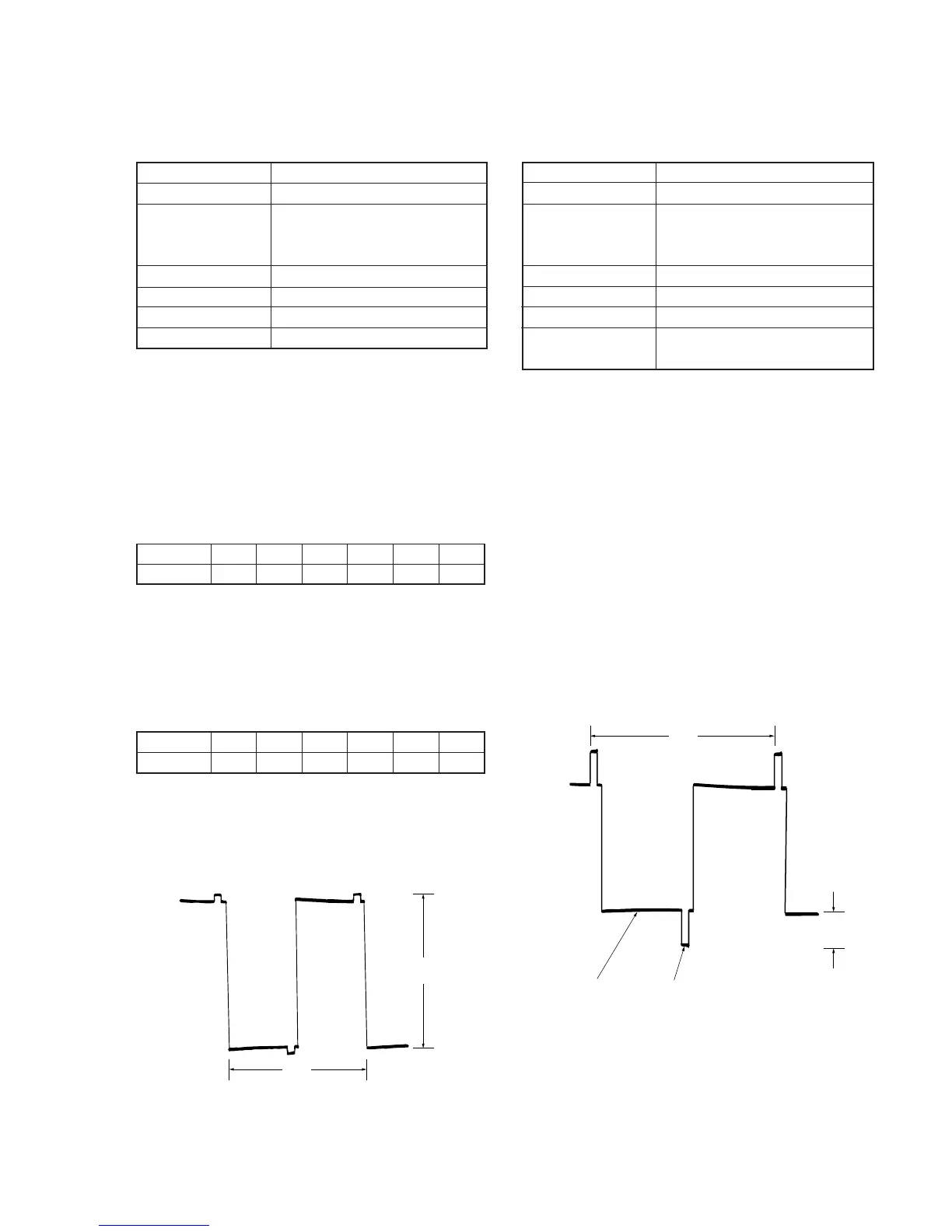
4) Change the data of page: D, address: D9, and set the voltage (A)
between the white 30% and pedestal to the specified value.
5) Press the PAUSE button of the adjusting remote commander.
6) Set data:00 to page: 2, address: 05.
7) Set data:00 to page: 2, address: 49.
8) Check that the specified value of “Bright Adjustment” is satisfied,
if not, perform “Bright Adjustment”.
Mode
Signal
Measurement Point
Measuring Instrument
Adjustment Page
Adjustment Address
Specified Value
VTR stop
No signal
Pin !ª of CN6202 (EVF VG) of
VC-183 board or pin 8 of IC4502
(G OUT) of VF-106 board
Oscilloscope
D
D8
A = 7.30 ± 0.1V
Address
Data
E8 E9 EA EB EC ED
00 46 00 C0 80 40
Note: Press the PAUSE button of the adjusting remote
commander each time to set the data.
3) Set data: 11 to page: 2, address: 05.
4) Change the data of page: D, address: D8, and set the voltage (A)
between the reversed waveform pedestal and non-reversed
waveform pedestal to the specified value.
5) Press the PAUSE button of the adjusting remote commander.
6) Input the following data to page: D, addresses: E8 to ED.
Address
Data
E8 E9 EA EB EC ED
3B 46 2C DF 82 40
Note: Press the PAUSE button of the adjusting remote
commander each time to set the data.
7) Set data: 00 to page: 1, address: 00.
8) Check that the specified value of “Contrast Adjustment” is
satisfied, if not, perform “Contrast Adjustment”.
A
2H
Mode
Signal
Measurement Point
Measuring Instrument
Adjustment Page
Adjustment Address
Specified Value
Pin !ª of CN6202 (EVF VG) of
VC-183 board or pin 8 of IC4502
(G OUT) of VF-106 board
VTR stop
No signal
Oscilloscope
D
D9
A = 1.80 ± 0.1V (NTSC)
A = 1.70 ± 0.1V (PAL)
2H
White 30%
pedestal
A
Fig. 6-1-12.
Fig. 6-1-13.


 To Next Page
 Loading...