6-22
5. Backlight Consumption Current Adjustment
(VF-106 board)
Adjust the luminance and color temperature of the back light.
If these are not correct, the image will be brighter or darker than
normal.
Note 1: If the oscilloscope is connected to other instruments,
disconnect them, and check that the oscilloscope is not
touching other instruments.
Note 2: Don’t connect the 680 Ω resistor to pin !ª of CN6202 (EVF
VG).
Adjusting method:
1) Adjust the power supply voltage so that the Pin 1, 2 voltage
(ACV UNREG) of DD-91 board CN3701 becomes 6.0 ± 0.1Vdc.
2) Set data: 01 to page: 1, address: 00.
3) Input the following data to page: D, addresses: E8 to ED.
6. White Balance Adjustment (VF-106 board)
Adjust to the proper white balance.
If it is not correct. the color reproducibility of the LCD panel will be
poor.
Mode
Signal
Measurement Point
Measuring Instrument
Adjustment Page
Adjustment Address
Specified Value
VTR stop (Adjustment mode 3)
No signal
CH1: Pin !ª of CN6202 (EVF VG) of
VC-183 board
GND: Pin 1, 2 of CN3701 (ACV
UNREG) of DD-91 board (Note 1)
Oscilloscope (DC range)
D
D5
A = 50.0 ± 1.0mV
Address
Data
E8 E9 EA EB EC ED
00 40 00 C0 80 40
Note: Press the PAUSE button of the adjusting remote
commander each time to set the data.
4) Set data:11 to page: 2, address: 05.
5) Check the GND level of the oscilloscope (ACV UNREG level).
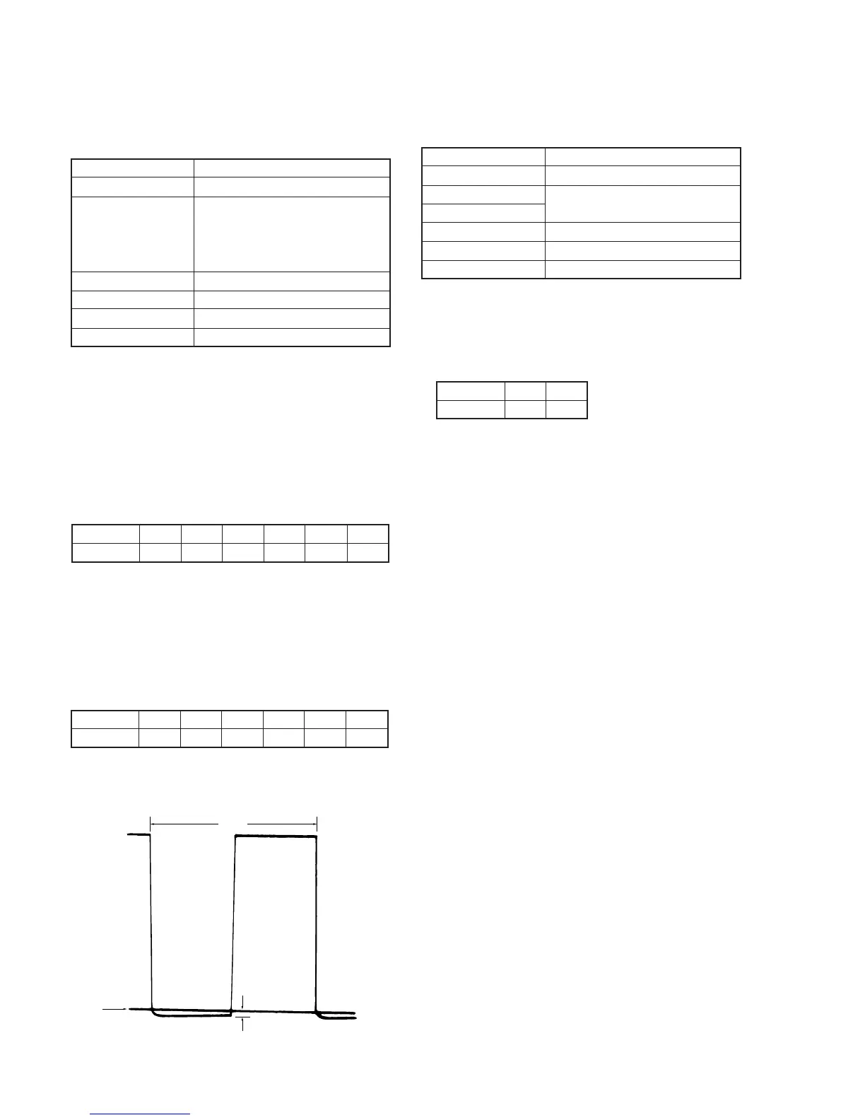
6) Change the data of page: D, address: D5, and set the voltage (A)
between the GND level and low level of EVF VG waveform to
the specified value.
7) Press the PAUSE button of the adjusting remote commander.
8) Input the following data to page: D, addresses: E8 to ED.
Address
Data
E8 E9 EA EB EC ED
3B 46 2C DF 82 40
Note:Press the PAUSE button of the adjusting remote
commander each time to set the data.
9) Set data: 00 to page: 1, address: 00.
Fig. 6-1-14.
A
2H
Oscilloscope
GND level
(ACV UNREG)
EVF VG
Mode
Signal
Measurement Point
Measuring Instrument
Adjustment Page
Adjustment Address
Specified Value
VTR stop
No signal
Check on the LCD display
D
DC, DD
The display should not be colored
Adjusting method:
1) Set data: 01 to page: 1, address: 00.
2) Set data: 11 to page: 2, address: 05.
3) Set data: 02 to page: 2, address: 49.
4) Set data: FF to page: 5, address: 00.
5) Set the data of page: D, address: DC and DD to the initial value.
Address
Data
DC DD
A1 B8
Note: Press the PAUSE button of the adjusting remote
commander each time to set the data.
6) Check that the LCD display is not colored. If it is, change the
data of address: DC and address: DD, and adjust so that the display
is not colored.
Note: To write in the non-volatile memory (EEPROM), press
the PAUSE button of the adjusting remote commander
each time to set the data.
7) Set data: 00 to page: 2, address: 05.
8) Set data: 00 to page: 2, address: 49.
9) Set data: 30 to page: 5, address: 00.
10) Set data: 00 to page: 1, address: 00.


 To Next Page
 Loading...