EasyManua.ls Logo

Sony DCR-TRV380 User Manual

Sony DCR-TRV380
64 pages
To Next Page IconTo Next Page
Page #1 background imageLoading...
Page #1 background image
SERVICE MANUAL
LEVEL 2
Link
SERVICE NOTE
DISASSEMBLY
BLOCK DIAGRAMS
FRAME SCHEMATIC DIAGRAMS
SCHEMATIC DIAGRAMS
PRINTED WIRING BOARDS
REPAIR PARTS LIST
SPECIFICATIONS
SERVICE NOTE
DISASSEMBLY
BLOCK DIAGRAMS
FRAME SCHEMATIC DIAGRAMS
SCHEMATIC DIAGRAMS
PRINTED WIRING BOARDS
REPAIR PARTS LIST
SPECIFICATIONS
Link
Revision History
Revision History
How to use
Acrobat Reader
How to use
Acrobat Reader
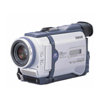
Photo: DCR-TRV480E
Ver 1.1 2004.12
M2000 MECHANISM
DIGITAL VIDEO CAMERA RECORDER
•For ADJUSTMENTS (SECTION 6), refer to SERVICE MANUAL, ADJ (9-876-781-51).
•For INSTRUCTION MANUAL, refer to SERVICE MANUAL, LEVEL1 (9-876-781-41).
•For MECHANISM ADJUSTMENTS, refer to the “8mm Video MECHANICAL ADJUSTMENT MANUAL IX
M2000 MECHANISM ” (9-929-861-11).
Reference No. search on printed wiring boards is available.
•Table for differences of function of each model.
•TO TAKE OUT A CASSETTE WHEN NOT EJECT (FORCE EJECT)
HELP: Sheet attachment positions and procedures of processing the flexible boards/harnesses are shown.
On the VC-345 board
This service manual provides the information that is premised
the circuit board replacement service and not intended repair
inside the VC-345 board.
Therefore, schematic diagrams, printed wiring boards, mounted
parts location and electrical parts list of the VC-345 board are
not shown.
The following pages are not shown.
Schematic diagrams ..................... Pages 4-9 to 4-44
Printed wiring boards .................... Pages 4-59 to 4-62
Waveforms .....................................
Pages 4-70 to 4-75
Mounted parts location ..................
Pages 4-77 and 4-78
Electrical parts list ......................... Pages 5-16 to 5-24
Sony EMCS Co.
2004L0500-1
©2004.12
Published by DI Technical Support Section
9-876-781-31
DCR-TRV380/TRV480/TRV480E
RMT-831
DCR-TRV480
US Model
Canadian Model
DCR-TRV480E
AEP Model
UK Model
North European Model
Australian Model
DCR-TRV380/
TRV480/
TRV480E
E Model
Question and Answer IconNeed help?

Do you have a question about the Sony DCR-TRV380 and is the answer not in the manual?

Sony DCR-TRV380 Specifications

General IconGeneral
BrandSony
ModelDCR-TRV380
CategoryCamcorder
LanguageEnglish

Summary

Service Note

Repair Notes and Power Supply Guidance

Essential notes for safe repair procedures and power supply during maintenance.

Force Eject Procedure

Method to manually remove a cassette when the eject mechanism fails.

Self-Diagnosis Function Overview

Explanation of the unit's self-diagnosis system and display for troubleshooting.

Self-Diagnosis Code Table

Detailed list of error codes, symptoms, and troubleshooting corrections.

Disassembly

Disassembly Flow Chart

Visual guide illustrating the step-by-step disassembly process.

Mechanism Deck Service Position

Instructions for setting up the mechanism deck for service checks.

LCD Service Position

Procedure for accessing the LCD unit for service adjustments.

Circuit and Flexible Boards Location

Diagrams showing the placement of internal circuit and flexible boards.

Block Diagrams

Printed Wiring Boards and Schematic Diagrams

Frame Schematic Diagram

Overall schematic diagram showing main component interconnections.

Schematic Diagrams

Detailed circuit schematics for various sections and boards.

Printed Wiring Boards

Layout diagrams showing component placement on circuit boards.

Waveforms

Visual reference for signal waveforms used in testing.

Mounted Parts Location

Diagrams indicating the physical placement of components on boards.

Repair Parts List

Exploded Views

Visual breakdowns of the camcorder's assemblies for part identification.

Electrical Parts List

Detailed list of electronic components with their part numbers.

Related product manuals