EasyManua.ls Logo

Sony Discman D-50MkII User Manual

Sony Discman D-50MkII
80 pages
To Next Page IconTo Next Page
Page #1 background imageLoading...
Page #1 background image
Ne
|
]
_
[REVISED
Discard
D-50MkH/D-7S
SERVICE
MANUAL
(No.
9-952-109-11)
previously
issued.
STEP/MIN
“SEC
Refer
to
BP-200
Service
Manual
issued
previously
for
information
of
rechargeable
battery
pack
supplied
with
this
set.
US
Model
Canadian
Model
‘D-SOMkII:
AEP
Model
UK
Model
_
E
Model
_
AUS
Model
FRENCH
Model
|
Dutch
Model
Pisthan
SPECIFICATIONS
System
Compact
disc
digital
audio
system
General
Disc
Compact
disc
Power
requirements
Lead
acid
battery
(closed
type)
Material:
GaAlAs
Wavelength:
780nm
Emission
duration:
Continuous
Laser
output:
Max.
0.4mvV*
*This
output
is
the
value
measured
at
a
distance
of
about
1.6
mm
from
the
objective
lens
surface
on
the
Optical
Pick-up
Block.
500r.p.m.
to
200r.p.m.
(CLV)
Laser
diode
properties
Spindie
speed
Scan
velocity
1.2-1.4misec.
Error
correction
Sony
Super
Strategy
Cross
Interleave
Reed
Solomon
Code
Number
of
channels
2
D-A
conversion
16-bit
linear
Frequency
response
20--20,000
Hz‘}dB
Total
harmonic
distortion
Less
than
0.008
%
Oynamic
range
More
than
90d8
(1
kHz)
Wow
and
flutter
Below
measurable
limit
Outputs
(at
9V
input
level)
Line
output
(stereo
minijack)
Output
level
1.6V
rms
Load
impedance
over
10
kilohms
Headphones
(stereo
minijack)
30
mW
+
30
MW
at
32
ohms
CAUTION
@
Use
of
controls
or
adjustments
or
performance
of
procedures
other
than
those
specified
herein
may
result
in
hazardous
radiation
exposure.
SAFETY-RELATED
COMPONENT
WARNING!!
COMPONENTS
IDENTIFIED
BY
SHADING
AND
MARK
A
ON
THE
SCHEMATIC
DIAGRAMS
AND
IN
THE
PARTS
LIST
ARE
CRITICAL
TO
SAFE
OPERATION.
REPLACE
THESE
COMPONENTS
WITH
SONY
PARTS
WHOSE
PART
NUMBERS
APPEAR
AS
SHOWN
IN
THIS
MANUAL
OR
IN
SUPPLEMENTS
PUBLISHED
BY
SONY.
using
Sony
BP-200
rechargeable
battery
pack
(supplied),
6V
Eight
IEC
designation
LR6
atkaline
batteries
(size
AA)
using
Sony
EBP-380
battery
case
(optional),
12V
DC
IN
9V
jack
accepts;
Sony
ac
power
adaptor
(supplied)
For
use
in
US,
Canadian
Model
on
120V
ac,
60
Hz
For
use
in
UK,
AUS
Model
on
240V
ac,
50
Hz
For
use
in
AEP,
Dutch
Model
on
220V
ac,
50
Hz
For
use
in
E
Model
on
110,
120,
220,
or
240V
ac,
50/60
Hz
Sony
DCC-120
car
battery
cord
(optional)
for
use
on
12V
car
battery
Power
consumption
2.6W
dc
Dimensions
Approx.
125.927
x
125.9mm
(w/hid)
(5x
1/,x5
inches)
not
incl.
inclined
part
(depth)
not
inct.
projecting
parts
and
controls
Approx.
126.9
«31.5
132.5
mm
(wihid)
(5x
1/,x5Y,
inches)
incl.
projecting
parts
and
controls
Weight
Approx.
510g
(11!b
2.02),
net
ATTENTION
AU
COMPOSANT
AYANT
RAPPORT
A
LA
SECURITE!
LES
COMPOSANTS
IDENTIFIES
PAR
UNE
TRAME
ET
UNE
MARQUE
A
SUR
LES
DIAGRAMMES
SCHE-
MATIQUES
ET
LA
LISTE
DES
PIECES
SONT
CRITIQUES
POUR
LA
SECURITE
DE
FONCTIONNEMENT.
NE
REM-
PLACER
CES
COMPOSANTS
QUE
PAR
DES
PIECES
SONY
DONT
LES
NUMEROS
SONT
DONNES
DANS
CE
MANUEL
OU
DANS
LES
SUPPLEMENTS
PUBLIES
PAR
SONY.
COMPACT
DISC
COMPACT
PLAYER
MICROFILM
SONY.
Question and Answer IconNeed help?

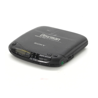
Do you have a question about the Sony Discman D-50MkII and is the answer not in the manual?

Sony Discman D-50MkII Specifications

General IconGeneral
TypePortable CD Player
ModelD-50MkII
BrandSony
Frequency response20 Hz - 20 kHz
Signal to Noise Ratio90 dB
Anti-Skip ProtectionYes
Dynamic Range90 dB
Disc formatCD
Digital converter1-bit
Power SupplyAA batteries or AC adapter
OutputHeadphone and Line Out

Summary

Product Specifications and Safety

General Specifications

Technical specifications for the CD player, including system and performance details.

Safety Warnings

Important safety precautions regarding radiation and critical components.

Product Overview and Maintenance

Key Features and Maintenance Procedures

Description of product features and instructions for cleaning and upkeep.

Troubleshooting Common Issues

Guide to resolving common problems like disc playback and sound issues.

Compact Disc Handling Guidelines

Recommendations for proper handling and care of compact discs.

Service Aid: Disc Teller Not Rotating

Service Aid: Disc Teller Not Rotating (Cont.)

Electrostatic Safety Precautions

Optical Pick-Up Handling and Grounding

Proper procedures for handling the optical pick-up block and grounding to prevent static damage.

Chip Component Identification Methods

EIAJ Coding Systems for Components

Explanation of 2-letter, 3-number, and 4-letter coding systems for chip components.

Replacing Chip Components

Precautions, Removal, and Connection Procedures

Guidance on safely replacing chip components, including removal and connection steps.

Circuit Board Repair and Layouts

Flexible Circuit Board Repair and Soldering Tips

Procedures for repairing flexible circuit boards and soldering iron tip maintenance.

PC Boards, Switch, and Motor Layout Diagram

Diagram illustrating the layout of PC boards, switches, and motors within the unit.

Service Mode Operation

Service Program Flow Chart

Flowchart detailing the service program execution and logic for diagnostics.

Laser Diode Emission Check Procedure

Controls and Indicators Overview

Front, Rear Panel, Display, and Play Modes

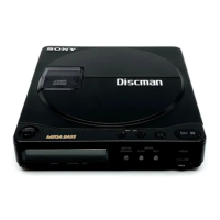
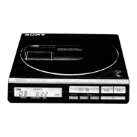
Description of front/rear controls, display window, and play mode indicators.

Battery Pack Recharging Instructions

Instructions on how to recharge the rechargeable battery pack.

Disc Playback Operations

Stopping, Pausing, and Using Time Counter

Procedures for stopping, pausing playback, and utilizing the time counter.

Searching for Selections and Specific Points

Using AMS and Search functions to locate selections or specific points on the disc.

Advanced Playback Modes

Repeat, Random, and Custom Order Playback

Instructions for repeat play, AB repeat, shuffle play, and RMS custom order playback.

Section 1: Outline

Circuit Description: System Control Microcomputer

Detailed circuit description of the 4-bit microcomputer system and its functions.

Pin Functions Reference (Table 1)

Pin Functions Reference (Table 1 Cont.)

Program Flow Chart and Servicing Note

Program Flow Chart

Flowchart detailing the service program execution and logic.

Charge Circuit Check Procedure

Procedure for checking the battery charging circuit.

Connection and Voltage Diagrams

Section 2: Disassembly and Reassembly

Disassembly Procedures and Mechanical Handling

Step-by-step disassembly instructions and notes on handling mechanical parts.

Mechanical Section Reassembly Procedures

Spindle Motor, Flexible Board, and Sled Motor Reassembly

Reassembly steps for spindle motor, flexible board, and sled motor sections.

Oil Supply, FOP, and Feed Rack Procedures

Procedures for oiling shafts, replacing FOP, and reassembling the feed rack.

Optical Pick-Up Block (FOP) Replacement

FOP Disassembly and Installation Steps

Detailed steps for disassembling and installing the optical pick-up block.

Section 3: Mechanical Adjustments

Turntable Height and Feed Screw Thrust Adjustment

Procedures for adjusting turntable height and feed screw thrust for optimal operation.

Section 3: Electrical Adjustments

Adjustment Notes, Preparation, and Basic Checks

General notes, preparation, and checks for sled motor and focus search.

PLL Frequency and Focus Bias Adjustment

Procedures for PLL frequency check/adjustment and focus bias adjustment.

RF Signal Reference Waveform (Eye Pattern)

Description and diagram of the expected RF signal eye pattern.

Tracking Balance and Sled Motor Adjustments

Tracking Balance Adjustment: Conditions and Procedure

Conditions and step-by-step procedure for adjusting tracking balance.

Sled Motor Offset: Conditions and Procedure

Conditions and procedure for checking and adjusting sled motor offset.

Tracking Gain Adjustment

Adjustment Procedure and Method Details

Procedure and method for adjusting tracking gain using VR control.

Tracking Gain Adjustment (Cont.)

Tracking Gain Adjustment (Cont.)

Adjustment Reference Points and Semiconductor Layouts

2.5V Reference and Adjustment References

Connecting point for 2.5V reference and references to related adjustment sections.

Semiconductor Lead Layouts

Diagrams showing lead layouts for various semiconductor components.

Semiconductor Lead Layouts (Cont.)

Section 4: Mounting Diagram

Mounting Diagram (Cont.)

Mounting Diagram (Cont.)

Mounting Diagram (Cont.)

Mounting Diagram (Cont.)

Section 5: Exploded Views and Parts List

Schematic Diagram Notes and Part Supply Info

Notes on schematic symbols, units, and supply status of mechanical parts.

Switch List and Component Details

List of switches and details on mechanical parts and components.

Comprehensive Parts List

Detailed list of all parts with part numbers, descriptions, and remarks.

Exploded Views and Parts List (Cont.)

Exploded Views and Parts List (Cont.)

Exploded Views and Parts List (Cont.)

Exploded Views and Parts List (Cont.)

Schematic Diagram

Schematic Diagram (Cont.)

Schematic Diagram (Cont.)

Schematic Diagram (Cont.)

Tape Path Adjustment Guide (SL-C/710/711)

NTSC and CCIR System Chassis Types

Lists chassis types for SL-C/710/711 models in NTSC and CCIR systems.

Section 1: SL-C/710 Type (NTSC) Tape Path Adjustment

Terminology and Preparations for NTSC Adjustment

Terminology for tape guides and preparation steps for NTSC tape path adjustment.

SL-C/710 Type (NTSC) Tape Path Adjustment (Cont.)

1-3. Entrance Side Adjustment Procedure

Procedure for adjusting entrance side guides for proper tape path alignment.

SL-C/710 Type (NTSC) Tape Path Adjustment (Cont.)

1-4. Exit Side Adjustment Procedure

Procedure for adjusting exit side guides and ACE head for proper tape path.

SL-C/710 Type (NTSC) Tape Path Adjustment (Cont.)

Audio/CTL Position Adjustment

Audio Head Azimuth and CTL Position Adjustment

Procedures for adjusting audio head azimuth and CTL head position.

ACE Assembly Position Adjustment Details

Details on mechanical and electrical adjustment of the ACE assembly.

Audio/CTL Position Adjustment (Cont.)

1-6. Audio Height Adjustment Procedure

Procedure for adjusting audio head height if necessary.

RF Output Waveform and Pairing Checks

Self-Recorded RF Output Waveform Check

Procedure to check the self-recorded RF output waveform.

Pairing Check Procedure

Procedure to check and match CH-A and CH-B RF output levels.

Tape Running Development Chart

Section 2: SL-C/710 Type (CCIR) Tape Path Adjustment

Terminology and Preparations for CCIR Adjustment

Terminology for tape guides and preparation steps for 711 CCIR tape path adjustment.

SL-C/710 Type (CCIR) Tape Path Adjustment (Cont.)

2-3. Entrance Side Adjustment Procedure

Procedure for adjusting entrance side guides for proper tape path alignment.

SL-C/710 Type (CCIR) Tape Path Adjustment (Cont.)

2-4. Exit Side Adjustment Procedure

Procedure for adjusting exit side guides and checking for tape curl and space.

SL-C/710 Type (CCIR) Tape Path Adjustment (Cont.)

Audio/CTL Position Adjustment

Audio Head Azimuth and CTL Position Adjustment

Procedures for adjusting audio head azimuth and CTL head position.

ACE Assembly Position Adjustment Details

Details on mechanical and electrical adjustment of the ACE assembly.

Audio/CTL Position Adjustment (Cont.)

2-6. Audio Height Adjustment Procedure

Procedure for adjusting audio head height if necessary.

RF Output Waveform and Pairing Checks

Self-Recorded RF Output Waveform Check

Procedure to check the self-recorded RF output waveform.

Pairing Check Procedure

Procedure to check and match CH-A and CH-B RF output levels.

Tape Running Development Chart

Section 3: 711 Type (NTSC) Tape Path Adjustment

Terminology and Preparations for NTSC Adjustment

Terminology for tape guides and preparation steps for 711 NTSC tape path adjustment.

711 Type (NTSC) Tape Path Adjustment (Cont.)

3-4. Exit Side Adjustment Procedure

Adjusting exit side guides and checking for tape curl and space.

711 Type (NTSC) Tape Path Adjustment (Cont.)

S Reel Damage Check and Audio/CTL Position Adjustment

S Reel Damage Check Procedure

Procedure to check for tape damage on the S reel.

Audio Head Azimuth and CTL Position Adjustment

Procedures for adjusting audio head azimuth and CTL head position.

Audio/CTL Position Adjustment (Cont.)

Tracking Control Center and CTL Head Position Adjustment

Adjusting tracking control center and CTL head position.

4-7. Audio Height Adjustment Procedure

Procedure for adjusting audio head height if necessary.

RF Output Waveform and Pairing Checks

Self-Recorded RF Output Waveform Check

Procedure to check the self-recorded RF output waveform.

Pairing Check Procedure

Procedure to check and match CH-A and CH-B RF output levels.

Tape Running Development Chart

Section 4: 711 Type (CCIR) Tape Path Adjustment

Terminology and Preparations for CCIR Adjustment

Terminology for tape guides and preparation steps for 711 CCIR tape path adjustment.

711 Type (CCIR) Tape Path Adjustment (Cont.)

4-3. Entrance Side Adjustment Procedure

Procedure for adjusting entrance side guides for proper tape path alignment.

711 Type (CCIR) Tape Path Adjustment (Cont.)

711 Type (CCIR) Tape Path Adjustment (Cont.)

4-4. Exit Side Adjustment Procedure

Adjusting exit side guides and checking for tape curl and space.

711 Type (CCIR) Tape Path Adjustment (Cont.)

S Reel Damage Check and Audio/CTL Position Adjustment

S Reel Damage Check Procedure

Procedure to check for tape damage on the S reel.

Audio Head Azimuth and CTL Position Adjustment

Procedures for adjusting audio head azimuth and CTL head position.

Audio/CTL Position Adjustment (Cont.)

4-7. Audio Height Adjustment Procedure

Procedure for adjusting audio head height if necessary.

RF Output Waveform and Pairing Checks

Self-Recorded RF Output Waveform Check

Procedure to check the self-recorded RF output waveform.

Pairing Check Procedure

Procedure to check and match CH-A and CH-B RF output levels.

Tape Running Development Chart

Service Manual Correction

Sled Motor Offset and Mounting Diagram Corrections

Corrections for sled motor offset adjustment and mounting diagrams on pages 9, 37, 38.

Schematic Diagram

Service Manual Supplement: Charge Circuit Check

Charge Circuit Check Procedure

Procedure for checking the battery charging circuit functionality.

Related product manuals