EasyManua.ls Logo

Sony Discman D-E440 User Manual

Sony Discman D-E440
27 pages
To Next Page IconTo Next Page
Page #1 background imageLoading...
Page #1 background image
Ver 1.0 1999.02
MICROFILM
D-E440/E441/E441SR/E443/E445/
E446CK/E449CK
SERVICE MANUAL
COMPACT DISC COMPACT PLAYER
SPECIFICATIONS
US Model
D-E441/E445/E446CK/E449CK
Canadian Model
D-E441/E445/E446CK
AEP Model
D-E440/E441/E441SR/E443/E445/E446CK
UK Model
D-E441/E441SR/E443/E445/E446CK
E Model
D-E441/E443/E445/E446CK
Australian Model
D-E441/E445/E446CK
Chinese Model
D-E441/E445
Model Name Using Similar Mechanism NEW
CD Mechanism Type CDM-2811EAA
Optical Pick-up Type DAX-11E
CD player
System
Compact disc digital audio system
Laser diode properties
Material: GaAIAs
Wavelength : λ= 780 nm
Emission duration: Continuous
Laser output : Less than 44.6 µW (This output
is the value measured at a distance of 200 mm
from the objective lens surface on the optical
pick-up block with 7 mm aperture. )
Error correction
Sony Super Strategy Cross Interleave Reed
Solomon Code
D-A conversion
1-bit quartz time-axis control
Frequency response
20 - 20,000 Hz
+1
dB (measured by EIAJ CP-
307)
-2
Output (at 4.5 V input level)
Headphones (stereo minijack)
15 mW + 15 mW at 16 ohms
Line output (stereo minijack)
Output level 0.7 V rms at 47 kilohms
Recommended load impedance over 10
kilohms
General
Power requirements
For the area code of the model you purchased,
check the upper left side of the bar code on the
package.
• Sony BP-DM10 Rechargeable battery:
2.4 V DC, Ni-Cd, 650 mAh
Sony BP-DM20 Rechargeable battery:
2.4 V DC, Ni-MH, 1,200 mAh
• Two LR6 (size AA) batteries: 3 V DC
AC power adaptor (DC IN 4.5 V jack):
US, Canadian, Central and South America
model: 120 V, 60 Hz
AEP, German, French, EE, E13 model:
220 - 230 V, 50/60 Hz
UK model: 230 - 240 V, 50 Hz
EA model: 110 - 240 V, 50/60 Hz
AUS model: 240 V, 50 Hz
E33 model: 100 - 240 V, 50/60 Hz
Hong Kong model: 220 V, 50/60 Hz
Chinese, Argentine model: 220 V, 50 Hz
• Sony CPM-300P mount plate for use on car
battery : 4.5V DC
Dimensions (w/h/d) (without projecting parts and
controls)
Approx. 129 x 28 x 146 mm
( 5
1
/8 x 1
1
/8 x 5
3
/4 in.)
Mass (without rechargeable battery)
Approx. 220 g (7.8 oz)
Operating temperature
5°C - 35°C (41°F - 95°F)
Supplied accessories
For the area code of the model you purchased,
check the upper left side of the bar code on the
package.
D-E440
Earphones (1)
D-E441
AC power adaptor (1)
Headphones (1)*
1
Earphones (1)*
2
AC plug adaptor (1)*
3
*
1
Supplied with US model
*
2
Not supplied with US model
*
3
Supplied with E33, E13 and EA models
Photo : D-E441
– Continued on page 2 –
Question and Answer IconNeed help?

Do you have a question about the Sony Discman D-E440 and is the answer not in the manual?

Sony Discman D-E440 Specifications

General IconGeneral
TypePortable CD Player
Digital OutputNo
Power source2 x AA batteries or AC adapter
DisplayLCD
Anti-Skip ProtectionYes
Frequency Response20Hz - 20kHz
Signal-to-Noise Ratio90dB
Disc formatCD
Audio Output3.5mm headphone jack
Playback ModesRepeat, Shuffle
Output Power5mW + 5mW (at 16 ohms)
Power Requirements3V DC (2 x AA batteries) or 4.5V AC adapter

Summary

SERVICE MANUAL

Model Name Using Similar Mechanism

Lists models sharing a similar mechanism for reference.

SPECIFICATIONS

Provides detailed technical specifications for the CD player.

SAFETY INFORMATION

DANGER

Warning about invisible laser radiation when interlock fails.

CAUTION

Precautionary statement on hazardous radiation exposure from controls.

SECTION 1 SERVICING NOTES

Handling the Optical Pick-up Block

Guidelines for safe handling of the optical pick-up block to prevent electrostatic breakdown.

Laser Diode Emission Check

Procedures for safely checking laser diode emission from the objective lens.

Optical Pick-up Replacement Checks

Pre-replacement checks and specifications for the optical pick-up block.

SECTION 2 GENERAL

Location and Function of Controls

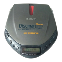
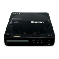
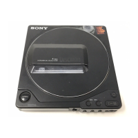
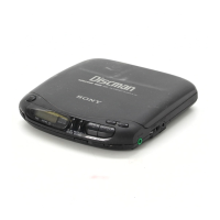
Identifies and explains the player's controls, buttons, and jacks.

SECTION 3 DISASSEMBLY

Lid Assembly Disassembly

Step-by-step guide to disassembling the upper lid assembly.

Cabinet Assemblies Disassembly

Steps for disassembling front/rear cabinet and MD assemblies.

Main Board Handling

SECTION 4 SERVICE MODE

Service Program Operation

Explanation of the service program and its operational methods.

SECTION 5 ADJUSTMENTS

Adjustment Precautions

General precautions and settings required before performing adjustments.

Focus Bias Check Procedure

Procedure for checking focus bias using an oscilloscope.

Focus and Tracking Gain Adjustment

Focus Gain Adjustment Procedure

Procedure for adjusting focus gain using RV503.

Tracking Gain Adjustment Procedure

Procedure for adjusting tracking gain using RV502.

Adjustment Location Guidance

SECTION 6 DIAGRAMS

IC Terminal Explanations

Details the pins and functions of IC terminals for system control.

System Block Diagram

Schematic Diagram

IC Block Diagrams (IC401, IC301)

IC Block Diagrams (IC502, IC601)

IC501 BA6386K Block Diagram

IC701 MPC17A51VMEL Block Diagram

SECTION 7 EXPLODED VIEWS

Cabinet Section Exploded View

Exploded view of the cabinet section and its parts.

Optical Pick-up Section Exploded View

SECTION 8 ELECTRICAL PARTS LIST

Related product manuals