EasyManua.ls Logo

Sony DSC-H10 - Cabinet Disassembly; Upper Cabinet Section

Sony DSC-H10
68 pages
Print Icon
To Next Page IconTo Next Page
To Previous Page IconTo Previous Page
Loading...
2-5
DSC-H10_L2
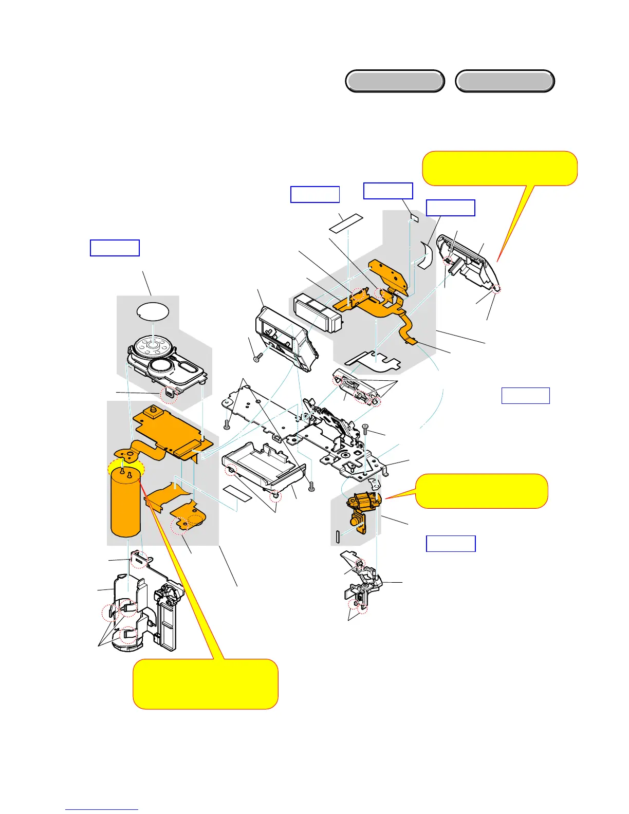
2-2-3. CABINET (UPPER) SECTION
Follow the disassembly in the numerical order given.
1 FL-179 Flexible Board (1-1 to 1-14)
2 ST-193 Flexible Board (2-1 to 2-7)
3 PL-048 Board (3-1 to 3-4)
EXPLODED VIEW
HARDWARE LIST
ST-193
1 FL-179
Flexible
Board
2-5 (#30)
2-1 (Claw)
2-2
(Claw)
2-4
(Claw)
2-3
3-1 (#23)
3-2
(Claw)
3-3
(Claw)
3-4
1-2 (#23)
1-3 (Claw)
1-4 (Claw)
1-6 (Claw)
1-9
(Claw)
1-12
(Claw)
1-13
1-14
1-7
1-10
(Claw)
1-11
Claw A
Claw B
1-5
2 ST-193
Flexible
Board
3 PL-048 Board
ST Assy
1-1
HELP02
HELP04
HELP05
HELP06
HELP03
HELP03
When install the ST case (Upper) assy,
attach claws A and B in alphabetical
order.
1-8
2-6 (Claw)
2-7
Note: Solderling caution
Be careful not to cut so long the leads
of capacitors (avoiding short-circuit).
Be sure not to touch
the copper leads or contacts.