EasyManua.ls Logo

Sony DSC-H400 User Manual

Sony DSC-H400
21 pages
To Next Page IconTo Next Page
Page #1 background imageLoading...
Page #1 background image
DSC-H400
Sony Corporation
SERVICE MANUAL
Published by Sony Techno Create Corporation
Ver. 1.0 2014.03
DIGITAL STILL CAMERA
Note:
Be sure to keep your PC used for service and checking of this unit
always updated with the latest version of your anti-virus software.
In case a virus affected unit was found during service, contact your
Service Headquarters.
US Model
Canadian Model
AEP Model
UK Model
Russian Model
E Model
Chinese Model
Brazilian Model
9-834-789-11
DSC-H400
2014C08-1
© 2014.03
Model information table
Model DSC-H400
Destination US, CND, E, BR AEP, UK, RU, E, CH
Color system NTSC PAL
GPS
Wi-Fi
NFC
Abbreviation
BR: Brazilian model
CH: Chinese model
CND: Canadian model
RU: Russian model
Question and Answer IconNeed help?

Do you have a question about the Sony DSC-H400 and is the answer not in the manual?

Sony DSC-H400 Specifications

General IconGeneral
Sensor TypeSuper HAD CCD
Effective Pixels20.1 MP
Optical Zoom63x
Focal Length4.4-277mm
ISO SensitivityISO 80-3200
LCD Screen Size3.0"
Video Resolution1280 x 720
Camera TypeBridge Camera
Dimensions129.6 x 95.0 x 122.3 mm
LCD Resolution460, 800 dots
Battery TypeAA
Weight628 g (with battery and memory stick)
Image Sensor Size1/2.3"
Maximum Aperturef/3.4-6.5
Digital ZoomApprox. 126x

Summary

SAFETY CHECK-OUT

Unleaded Solder Handling Precautions

Guidelines for handling unleaded solder, including temperature and application.

Critical Component Replacement Warning

Components critical for safe operation must be replaced with specified Sony parts.

SPECIFICATIONS

System and Image Specifications

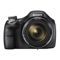
Details on image device, lens, file format, flash, burst shooting, and recording media.

Power, General, and Battery Information

Details on AC adaptor, battery pack, power consumption, and environmental limits.

EXPLODED VIEWS

SERVICE NOTE

Flash Capacitor Discharging Procedure

Procedure for safely discharging the flash capacitor using a short jig.

DISASSEMBLY & ASSEMBLY

Identifying Disassembly Parts

Diagram illustrating major components for disassembly and assembly.

Overall Block Diagram

Schematic showing the main functional blocks and their interconnections.

Related product manuals