Do you have a question about the Sony DSC-H5 and is the answer not in the manual?
Explanation of the camera's self-diagnosis display system and error codes.
Procedures for managing data within the camera's internal memory.
Steps to take after resolving a flash error, including re-initializing settings.
Precautions and required checks after SY-150 board replacement.
Procedure to verify and set default data for video output.
Procedure to check and set the initial language data after board replacement.
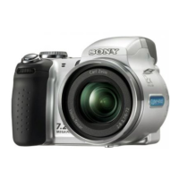
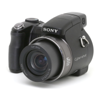
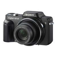
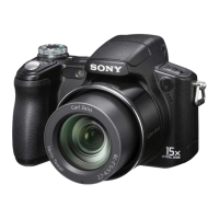
Detailed specifications for the camera system, including image sensor, lens, and exposure.
Information on external connections like A/V OUT and USB.
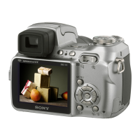
Specifications related to the camera's LCD display panel.
Details about the camera's electronic viewfinder specifications.
Power requirements, operating temperatures, and dimensions of the camera.
Procedures to ensure safety after repair, before returning the unit to the customer.
Guidelines and characteristics for using unleaded solder during repairs.
Warning about critical safety components requiring specific replacement parts.
Warning regarding battery replacement safety and proper handling.
Important notes regarding handling flat cables, flexible boards, and connectors during repair.
Critical procedure for safely discharging the high-voltage capacitor before work.
Instructions for preparing a short jig tool required for capacitor discharge.
Step-by-step visual guide for disassembling the camera unit.
Guidance on attaching the fuse replacement caution label to the SY-150 board.
Instructions for correctly routing loudspeaker harnesses during assembly.
Guidance on routing battery terminal board harnesses during assembly.
Instructions for routing ST section harnesses.
Further instructions for routing ST section harnesses.
Guidance on soldering harnesses according to color coding.
Instructions for installing the microphone correctly.
Procedure for removing the lens ring, including screw and sheet metal removal.
First part of the overall system block diagram, showing major components and interconnections.
Second part of the overall system block diagram, detailing further component connections.
First part of the power block diagram, illustrating power distribution and circuits.
Second part of the power block diagram, showing remaining power circuits and connections.
A high-level overview diagram showing the physical layout of boards and major components.
General notes applicable to all schematic diagrams, including component identification and measurement conditions.
Schematic diagram for the CD-617 board, focusing on the CCD imager and associated circuitry.
Schematic diagram for the SW-471 board, covering LCD back light and function switches.
Schematic diagram for the CK-161 flexible board, related to the LCD panel.
Schematic diagram for the ST-142 board, primarily for the flash drive.
Schematic diagram for the ST-144 board, related to the flash unit.
Schematic diagram for the PL-045 board, which controls the plunger mechanism.
Schematic diagram for the MS-305 board, associated with the memory stick interface.
Schematic diagram for the control switch block, including mode/jog dial functions.
Schematic diagram for the AF-105 flexible board, covering AF LED and lens cover switch.
Schematic diagram for the JK-306 flexible board, related to AV/USB jacks.
Schematic diagram for the CD-621 flexible board, related to the SY-CD relay.
Schematic diagram for the SW-478 flexible board, related to the SY-SW relay.
Schematic diagram for the MS-030 flexible flat cable, related to the SY-MS relay.
Schematic diagram for the ST-003 flexible flat cable, related to the SY-ST relay.
General notes applicable to printed wiring boards, including solder types and component markings.
Printed wiring board layout for the CD-617 board, side A and side B.
Printed wiring board layout for the SW-471 board, side A and side B.
Printed wiring board layout for the ST-142 board, side A and side B.
Printed wiring board layout for the ST-144 board.
Printed wiring board layout for the MS-305 board, side A and side B.
Printed wiring board layout for the PL-045 board, side A and side B.
Printed wiring board layout for the AF-105 flexible board.
Printed wiring board layout for the JK-306 flexible board.
Printed wiring board layout for the CD-621 flexible board.
Printed wiring board layout for the SW-478 flexible board.
Printed wiring board layout for the CK-161 flexible board.
Diagrams showing the physical location of components on specific boards.
Visual guides showing how the camera is assembled, with parts labeled.
Exploded view and parts list for the overall camera section.
Exploded view and parts list specific to the LCD section of the camera.
Exploded view and parts list for the main internal section of the camera.
Exploded view and parts list for the lens assembly.
Exploded view and parts list for the camera's front cabinet assembly.
Exploded view and parts list for the ST section of the camera.
Comprehensive list of electrical components with part numbers and descriptions.
List of supplied accessories for the camera.
Important notes regarding part numbering, stocking, and standardization.
Table indicating language support for different regional models.
Detailed exploded view of the camera's overall assembly and parts.
Exploded view and parts list for the overall camera section.
Exploded view and parts list specific to the LCD section of the camera.
Exploded view and parts list for the main internal section of the camera.
Exploded view and parts list for the lens assembly.
Exploded view and parts list for the camera's front cabinet assembly.
Exploded view and parts list for the ST section of the camera.
List of accessories that should be supplied with the camcorder.
List of additional accessories and their corresponding instruction manuals.
Electrical parts list for the AF-105 flexible board.
Electrical parts list for the CD-617 board.
Electrical parts list for the CK-161 board.
Electrical parts list for the JK-306 flexible board.
Electrical parts list for the MS-305 board.
Electrical parts list for the PL-045 board.
Electrical parts list for the ST-142 board.
Electrical parts list for the ST-144 board.
Electrical parts list for the SW-471 board.
Electrical parts list for the SY-150 board.
Initial release of the service manual.
First revision, including corrections to various sections of the manual.
| Sensor Resolution | 7.2 Megapixels |
|---|---|
| Optical Zoom | 12x |
| Digital Zoom | 2x |
| Display Size | 3.0 inches |
| ISO Sensitivity | 80 - 1000 |
| Storage Media | Memory Stick Duo/PRO Duo |
| Camera Type | Compact |
| Sensor Type | CCD |
| Minimum Shutter Speed | 30 sec |
| Focal Length | 36 - 432 mm (35mm equivalent) |
| Aperture Range | f/2.8 - f/3.7 |
| Battery Type | AA batteries (2) (NiMH recommended) |
| Sensor Size | 1/2.5 inches |
| LCD Screen Resolution | 230, 000 dots |