DSC-W370
2-5
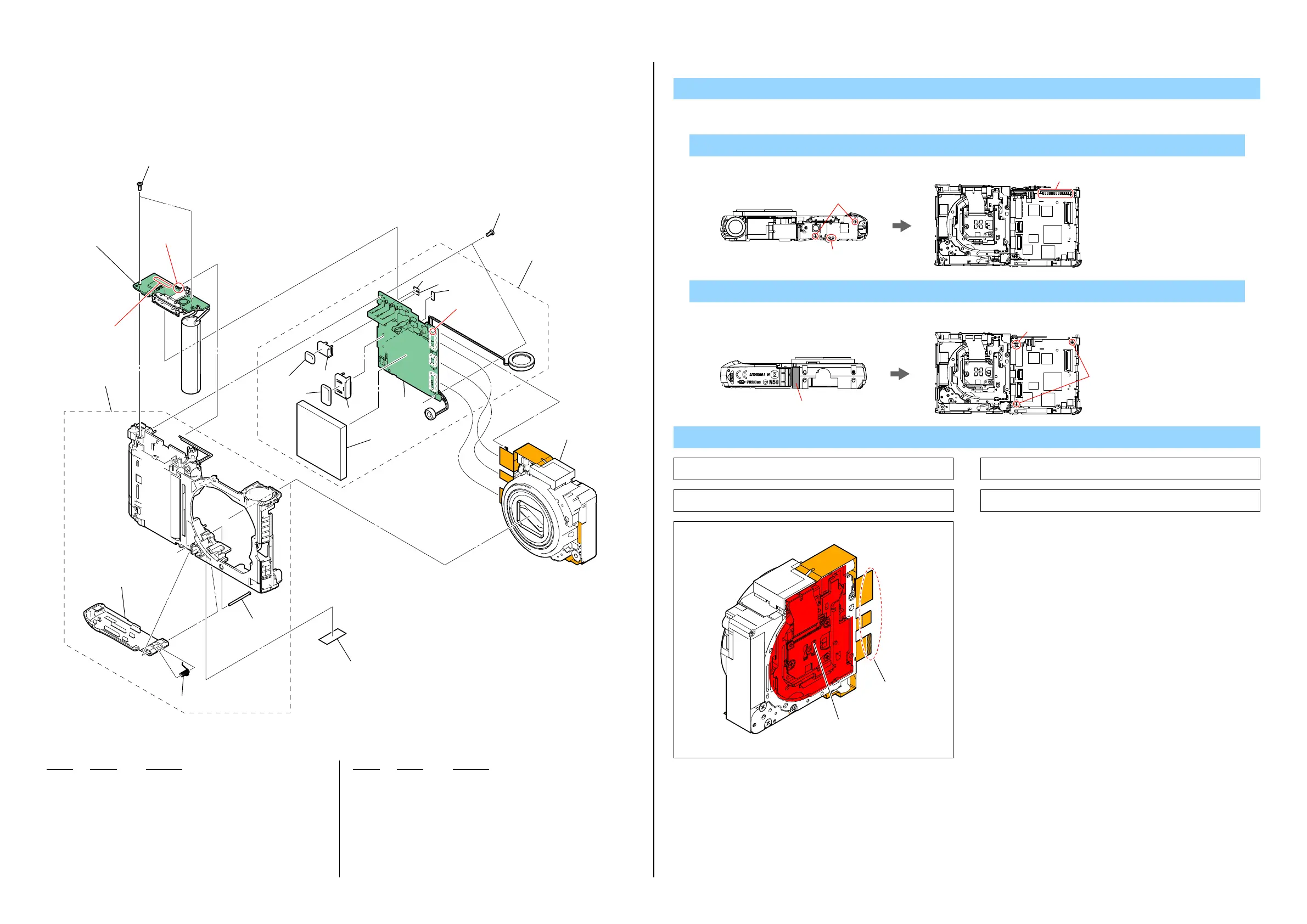
2-1-3. MAIN FRAME SECTION
ns:notsupplied
1. Removetonumericalorder(8 to qa)intheleftfigure.
DISASSEMBLY
Ref. No. Part No. Description
Ref. No. Part No. Description
101 4-181-525-01 BT COVER
102 X-2547-199-1 MAIN FRAME ASSY
103 4-179-239-01 STROBE UNIT (Note1)
104 4-179-238-01 MAIN BOARD (Note2, 3)
* 105 1-820-333-11 MULTI CONNECTOR (REC) 8P
106 4-180-525-01 CONNECTOR, HDMI C
107 1-822-837-21 CARD CONNECTOR
108 A-1766-461-A LENS ASSY (Note4, 5)
*0F1 1-523-038-31 FUSE, MICRO (0.25A/24V)
0 F2 1-576-415-11 FUSE, MICRO (1608 TYPE) (2A/32V)
0 F3 1-576-415-11 FUSE, MICRO (1608 TYPE) (2A/32V)
#S4 4-179-232-01 TAPPING_M1.4_3.5_SVR_AB
8 Unsolder (8-1) → #S4 X 2→ Unsolder (8-2)
9 Tape Remove (9-1) → Unsolder (9-2) → #S4 X 2
Note5: BecarefulabouttheLensAssy.
Note
Note1: Referto“Assembly-3:SolderingandRoutingLEDLampHarness
ofStrobeUnit”whenyouassemble.
Note3: Refer to “Assembly-2:Routing Microphone Harness of Main
FrameAssy”whenyouassemble.
Note2: Referto“Assembly-1:RoutingSpeakerHarnessofMainFrame
Assy”whenyouassemble.
Back ViewTop View
Solder
Solder
#S4
Back ViewBottom View
#S4
Solder
Tape
101
#S4
qa�102
8�103 (Note1)
107
106
105
9�104 (Note2, 3)
0�108 (Note4, 5)
#S4
ns
F2
F3
F1
ns
ns
ns
ns
ns
9-1
8(Solder)
8-2
8(Solder)
8-1
9(Solder)
9-2
Note4: CCDisincludedintheLensAssy.
NeverdisassembletheLensAssy.
Don't press the
Sensor holder
Keep these
Pins clean

 Loading...