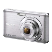
DSC-W370
2-1
2. REPAIR PARTS LIST
Follow the disassembly in the numerical order given.
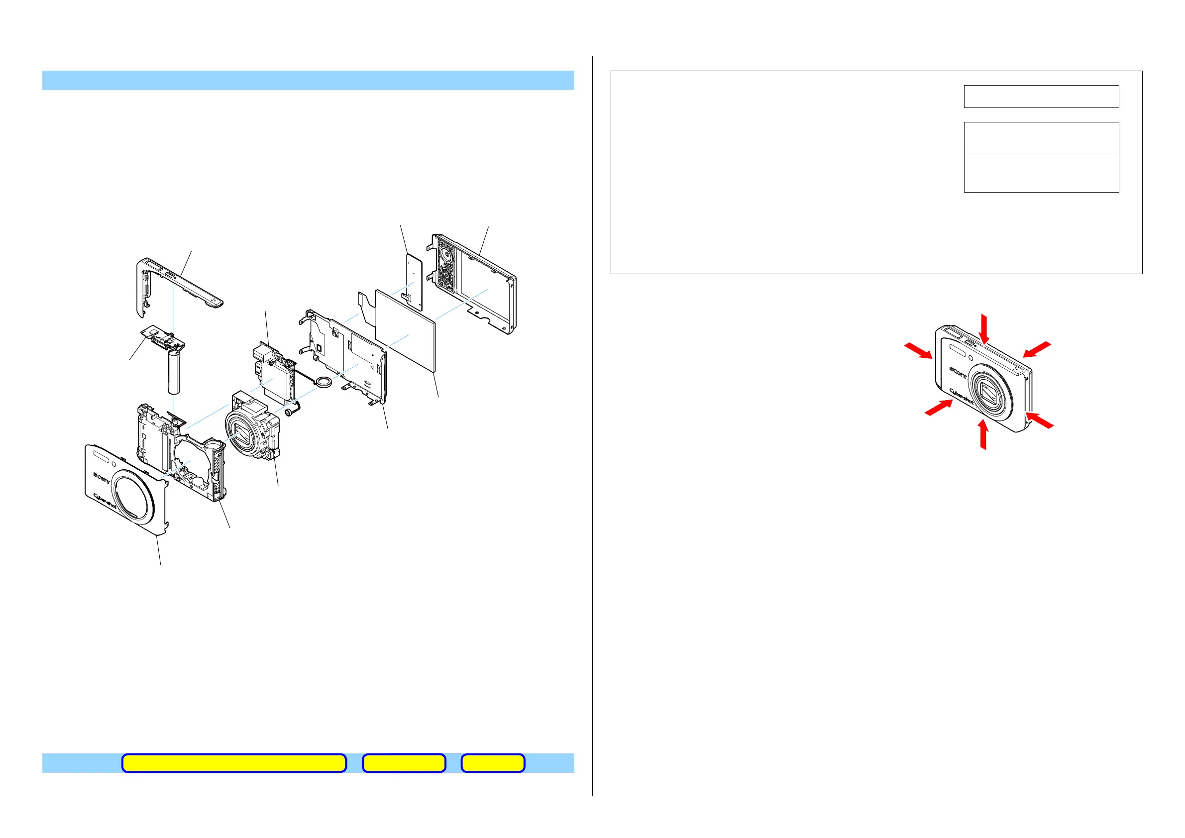
IDENTIFYING PARTS
View Position
(ENGLISH)
NOTE:
• -XX,-Xmeanstandardizedparts,sotheymayhavesomedifferencesfromtheoriginalone.
• Itemsmarked“*”arenotstockedsincetheyareseldomrequiredforroutineservice.Some
delayshouldbeanticipatedwhenorderingtheseitems.
• Themechanicalpartswithnoreferencenumberintheexplodedviewsarenotsupplied.
• Duetostandardization,replacementsinthepartslistmaybedifferentfromthepartsspeci-
fiedinthediagramsorthecomponentsusedontheset.
• ColorIndicationofAppearanceParts
Example:
(SILVER):Cabinet’sColor
(Silver) :PartsColor
The components identified by mark 0 or
dottedlinewithmark0arecriticalforsafety.
Replaceonlywithpartnumberspecified.
Lescomposantsidentifiésparunemarque
0sontcritiquespourlasécurité.
Nelesremplacerqueparunepièceportant
lenumérospécifié.
Whenindicatingpartsbyreference
number,pleaseincludetheboardname.
• Abbreviation
AUS :Australianmodel
CND :Canadianmodel
Top View
Back View
Right View
Bottom View
Front View
Left View
ACCESSORIES
Link
ACCESSORIES ASSEMBLYDISCHARGING OF THE CHARGING CAPACITOR
1 Rear Cabinet Assy
2 Front Cabinet Assy
3 Top Cover Assy
5 SW Board
6 LCD Bracket
7 LCD Module
8 Strobe Unit
9 Main Board
0 Lens Assy
qa Main Frame Assy
 Loading...