Do you have a question about the Sony FD TRINITRON KV-21FX30B and is the answer not in the manual?
Guide to initial TV setup and automatic channel scanning.
Explains navigation and use of the on-screen menu system.
Explains Fastext service for quick page access.
Procedure for removing the television's rear cover.
How to disconnect speaker connectors during disassembly.
Step-by-step removal of the speaker box.
Process for taking apart the speaker box.
Steps for removing the A Board Printed Wiring Board.
Correct positioning of the TV for servicing.
Guidelines for managing wires during repair.
Detailed procedure for removing the picture tube.
Adjusting the beam landing for picture alignment.
Procedure for adjusting screen convergence.
Adjusting geometric picture distortions.
Correction for Horizontal and Vertical Linearity.
Adjusting Yellow-Cyan-Hue.
Adjusting Top, Left, and Vertical settings.
Correcting convergence issues in screen corners.
Adjusting focus for a clear picture.
Adjusting screen grid voltage and white balance.
Performing electrical adjustments using the remote commander.
Adjusting sub-brightness for optimal display.
Adjusting sub-contrast for optimal display.
Adjusting sub-colour for accurate color reproduction.
Adjusting tuner Automatic Gain Control.
Accessing and using Test Mode 1 functions.
Accessing and using Test Mode 2 functions.
Overall system block diagrams illustrating signal flow.
Visual guide to the location of circuit boards.
Contains schematic and wiring diagrams for components.
Displays waveform data for the C Board.
Exploded view of the television chassis components.
Exploded view of the picture tube assembly.
Details the capabilities of the TRACE repair software.
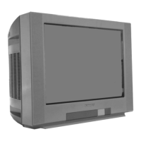
| Screen Size | 21 inches |
|---|---|
| Display Type | CRT |
| Screen Type | Flat |
| Aspect Ratio | 4:3 |
| Audio Output | 2 x 5W |
| Tuner | PAL/SECAM |
| Inputs | Composite, S-Video |
| Remote Control | Included |