EasyManua.ls Logo

Sony FD Trinitron KV-29FX65E User Manual

Sony FD Trinitron KV-29FX65E
84 pages
To Next Page IconTo Next Page
Page #1 background imageLoading...
Page #1 background image
1
SERVICE MANUAL
AE-5
CHASSIS
MODEL
COMMANDER DEST CHASSIS NO.
KV-29FX65B
RM-887 FRENCH SCC-Q13H-A
KV-29FX65E
RM-887 ESP SCC-Q14H-A
MODEL
COMMANDER DEST CHASSIS NO.
KV-29FX65K
RM-887 OIRT SCC-Q16L-A
p
- +
4
MONO
4
L/G/S/I
R/D/D/D
s
4
Question and Answer IconNeed help?

Do you have a question about the Sony FD Trinitron KV-29FX65E and is the answer not in the manual?

Sony FD Trinitron KV-29FX65E Specifications

General IconGeneral
BrandSony
ModelFD Trinitron KV-29FX65E
CategoryTV
LanguageEnglish

Summary

AE-5 SELF DIAGNOSTIC SOFTWARE

Diagnostic Item Description

Table detailing diagnostic items, LED flashes, probable causes, and detected symptoms.

Error Detection Monitor

Error Monitor Menu

How to enter and view the error monitor menu and stored errors.

Error Reader Display

Displaying actual error codes using the error reader tool.

SECTION 1 GENERAL

Tuning your TV

Steps to tune the TV to broadcast channels and set language/country.

Using the TV menu system

Guide to adjusting picture and sound settings via the TV menu.

Operation Using the TV menu system

Adjusting the picture and sound

Guide to adjusting picture and sound settings via the TV menu.

Sound Control

Adjusting sound settings like Equaliser Mode, Balance, Loudness, etc.

SECTION 2 DISASSEMBLY

2-11. Picture Tube Removal

Procedure for safely removing the picture tube, including anode cap.

SECTION 3 SET-UP ADJUSTMENTS

3-1. Beam Landing

Adjusting the CRT beam landing and purity.

3-2. Convergence

Adjusting screen centre convergence using static convergence magnets.

Correction for HMC and VMC

Correcting horizontal and vertical mis-convergence using BMC magnets.

3-3. Focus, Screen (G2) Adjustment

Adjusting focus and G2 for optimal screen focus.

3-4. White Balance Adjustment

Adjusting white balance using the service mode and remote commander.

SECTION 4 CIRCUIT ADJUSTMENTS

4-1. Electrical Adjustments

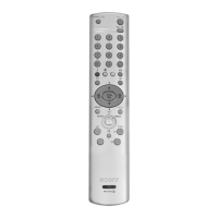
Service adjustments performed using the remote commander RM-887.

How to enter into the Service Mode

Step-by-step guide to entering the TV's service mode.

Initialising Menu

Model Setting

Selecting the TV model to set up features and hardware resources.

4-3. TEST MODE 2

Test Mode 2 Functions

Description of functions available in Test Mode 2 by selecting numbers.

5-2. CIRCUIT BOARD LOCATION

5-3. SCHEMATIC DIAGRAMS AND PRINTED WIRING BOARDS

Location of circuit boards and access to schematic diagrams.

E [R, G, B OUT CHROMA]

M1 [PRINTED WIRING BOARD (A side) ]

M1 MICROPROCESSOR & TEXT DECODER

M1 [MICROPROCESSOR AND TEXT DECODER]

Schematic diagram of the M1 microprocessor and text decoder.

D1 [DEFLECTION]

D1 DEFLECTION

Schematic diagram for the D1 deflection circuit.

J [INTERFACE/AUDIO/CHROMA/G COMB FILTER]

VM [PRINTED WIRING BOARD ]

5-5. IC BLOCK DIAGRAMS

SECTION 6 EXPLODED VIEWS

6-1. CHASSIS

Exploded view of the TV chassis and its components.

F4 BOARD COMPLETE Parts List

F1 BOARD COMPLETE Parts List

A Board, Variant Parts KV-29FX65B/29FX65E/29FX65K

TRANCE

TRACE Interface and Software

Information about the TRACE repair assistance tool and its software.

Related product manuals